Page 67
Corp. 1244-L9
Typical Unit Wiring Diagrams
The indoor wiring diagram location is on the inside of the cabinet at the terminal connection end. To access the diagram will
required removal of the cabinet. The wiring diagram on the outdoor unit is located on the top of the control box.
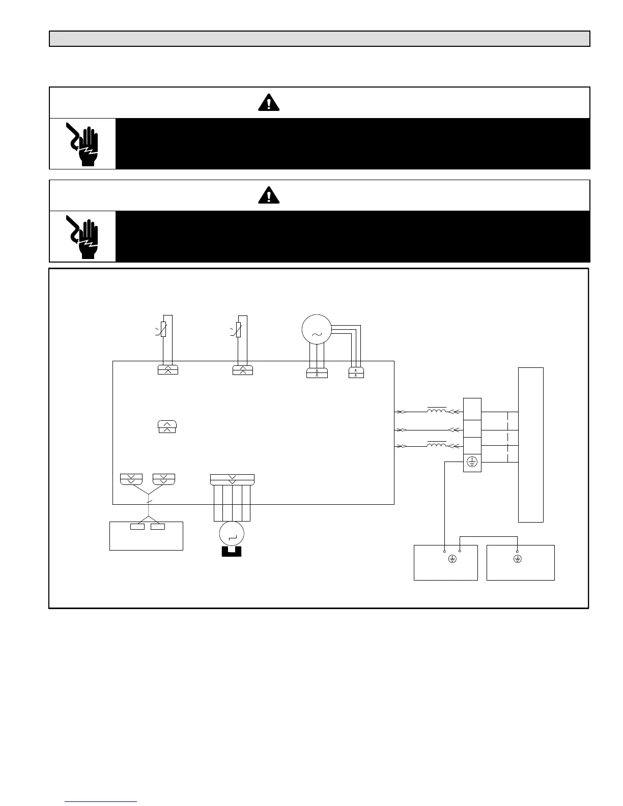
WARNING
Electric Shock Hazard. Can cause injury or death. Unit must be grounded in accordance with national and
local codes.
Line voltage is present at all components when unit is not in operation. Disconnect all remote electric power
supplies before opening access panel or cover. Unit may have multiple power supplies.
WARNING
Delayed Electric Shock Hazard
Capacitors in this unit may hold charge. Do not remove this cover or service this area for 2 minutes after
the main power has been removed.
TYPICAL INDOOR UNIT WIRING DIAGRAM — 09 THROUGH 18 KBTU SYSTEMS (208 / 230V)
FIGURE 74
0
TEMP. SENSOR
TEMP. SENSOR
AC−L
BK
G
ROOM
TUBE
M2
SWING−UD
ROOM
RT2
AP2
BN
PG
YEGN(GN)
0
M1
BU
FAN
OUTDOOR UNIT
2
3
XT
N(1)
TUBE
RT1
SWING
MOTOR
COM−OUT
N
PGF
MOTOR
CAP
JUMP
DISP2
DISP1
AP1
RECEIVER AND
DISPLAY BOARD
G
YEGN(GN)
EVAPORATOR
ELECTRIC BOX
 Loading...