Page 17
Corp. 1244-L9
NOTE — Stranded wire must be used to connect the
outdoor unit to the indoor unit. The stranded wire is
necessary to ensure proper system communication and
operation.
SUPPLY POWER
Size per unit nameplate and local and national codes.
WIRING CONNECTIONS
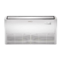
1. Remove access panel.
2. Route all wiring to outdoor unit through the wire routing
plate.
3. Connect the control wiring and power supply wiring per
the figures that follow.
4. The unit must be grounded according to local codes.
5. Secure wiring using built-in wire strain relief.
ACCESS PLATE
ROUTE WIRES
THROUGH
ROUTING
PLATE
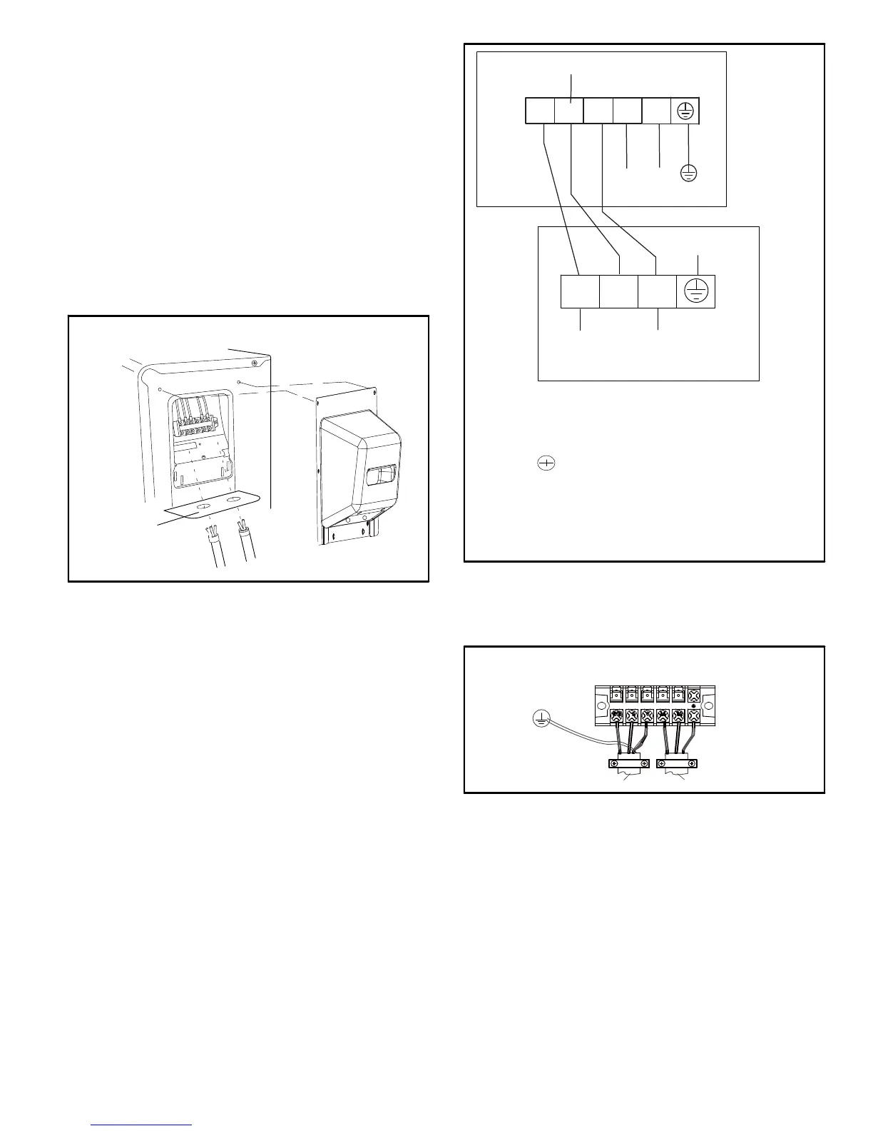
OUTDOOR UNIT ELECTRICAL CONNECTIONS
FIGURE 29
OUTDOOR UNIT
INDOOR UNIT
N(1)
23L1
L2
L2
L1
POWER
COMMUNICATION
N(1)
2
3
(L1)
(L2)
GROUND
(COMMUNICATION)
TERMINAL LEGEND
N(1) = L1
2 = Communication line
3 = L2
= Ground
IMPORTANT
Check indoor to outdoor field wiring to confirm (N) 1
from indoor goes to (N) 1 outdoor, terminal 2 from indoor
goes to terminal 2 outdoors and terminal 3 indoors goes
to terminal 3 in outdoor.
FIGURE 30
6. Connect the green/yellow ground wire to the ground
terminal.
7. Use the strain relief to secure the cabling (figure 31).
OUTDOOR UNIT
TERMINAL BLOCK
TO POWER SUPPLY
TO INDOOR UNIT
TYPICAL UNIT STRAIN RELIEF
FIGURE 31
WIRING DIAGRAM SYMBOLS AND COLOR CODES
The following tables identify the wiring color codes
and ground symbol used in the following wiring
diagrams.
 Loading...