13
Refrigerant Piping Connections
Both liquid and gas (vapor) lines must be individually
insulated.
Field piping consists of two fi eld-provided copper re-
frigerant lines connected to the outdoor unit. These
lines carry the liquid and vapor refrigerant to and
from the indoor unit(s).
• The three-ton VPA036H4 can provide cooling to
as many as fi ve indoor units.
• The four-ton VPA048H4 can serve up to seven
indoor units.
• The fi ve-ton VPA060H4 can serve up to nine in-
door units.
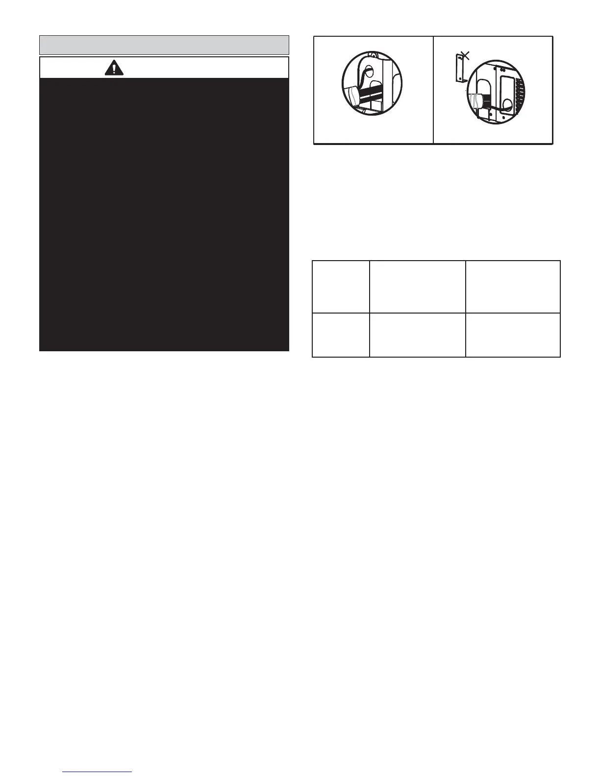
Refrigerant piping and wiring connections can be
brought into the outdoor unit through openings pro-
vided in the front and side of the unit. See Figure 16.
UNIT FRONT UNIT SIDE
REMOVE COVER PLATE
TO FACILITATE PIPING.
Figure 16. Refrigerant Piping / Wiring Inlets
Table 1 lists the connection sizes at the outdoor
unit. The connections are made using the provided
brass fl are nuts at the end of the refrigerant piping
connections. Both liquid and gas (vapor) lines must
be individually insulated.
Model Liquid Line Gas (Vapor) Line
VPA036H4
VPA048H4
VPA060H4
3/8 in. 3/4 in.
Table 1. Refrigerant Piping Connections
WARNING
Refrigerant leaks are unlikely; however, if a
refrigerant leak occurs, open a door or windows to
dilute the refrigerant in the room. Turn off the unit
and all other appliances that may cause a spark.
Call a licensed professional HVAC technician (or
equivalent) to repair the leak.
Use only R410A refrigerant to charge this system.
Use of other refrigerant or gas will damage the
equipment.
Do not allow air or other contaminants to enter
system during installation of refrigerant piping.
Contaminants will result in lower system capacity
and abnormally high operating pressures and may
result in system failure or explosion.
Insulate all refrigerant piping.
Refrigerant pipes may be very hot during unit
operation. Do not allow contact between wiring
and bare copper pipes.
After refrigerant piping connections have been
completed, check the system for leaks per
commissioning instructions.
 Loading...