6
Installation
It is important to locate the unit where it can be accessed
for service in the future. Refer to unit dimensions on Page
3 for exact locations of suspension brackets, return air
and supply air openings.
• Make sure that the structural ceiling is able to support
the weight of the indoor unit. It may be necessary to
add extra support.
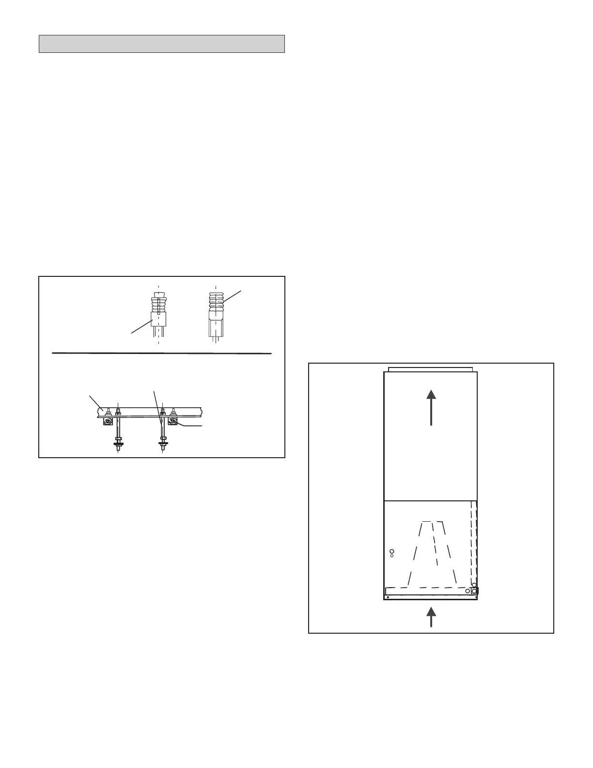
• Install suspension rods in the structural ceiling or
concrete slab in a suitable location.
• If the structural ceiling is constructed of concrete,
install anchors to accept four ⅜” threaded rods to
suspend the indoor unit. If the structural ceiling
includes wooden joists, use angle iron or Unistrut
channel xed securely in place to accept the ⅜”
threaded rods. See gure 1.
• Use either a mechanical lifting device or a minimum of
two people to raise the unit.
• If necessary, install a eld-provided isolation grommet
to prevent transmission of vibration from unit to
structural ceiling.
• If the unit is being installed in an application that
includes a sheet rock (plasterboard) ceiling, it is
recommended to install an access panel in a suitable
location to allow nal connection of the refrigerant
piping, condensate line and electrical connections.
• This will also allow access for future maintenance.
• For ease of installation, it is best to make any
necessary coil conguration changes before setting
the air handler in place.
Figure 2. Upow Conguration
NOTE - When the unit is installed in horizontal applications,
a secondary drain pan is recommended. Refer to local
codes. Adequate support must be provided to ensure
cabinet integrity. Ensure that there is adequate room
to remove service and access panels if installing in the
horizontal position.
Upow Application
1. The air handler must be supported on the bottom only
and set on a suitable base or a eld-supplied support
frame. Securely attach the air handler to the oor or
support frame.
2. If installing a unit in an vertical application, remove the
horizontal drain pan.
3. Place the unit in the desired location and properly
slope the unit, see page 11. Connect the return and
supply air plenums as required using sheet metal
screws.
4. Determine knockouts required for drain line
connections.
5. With access door removed, remove drain line opening
to install drain lines.
6. If the unit is intended to be used with an “open” return
air path, ensure there is at least 14” of clearance
below the unit.
Anchor
CONCRETE CEILING
USING ANCHORS
ANGLE IRON
ACROSS
WOODEN JOISTS
Threaded rod
Angle iron bolted
in place across
wooden joists
Wooden joist
Threaded rod
Figure 1. Locate Threaded Rods
 Loading...