Page 11
XC14 SERIES
Brazing Connections
Use the following procedure to braze the line set to the new
air conditioner unit. Figure 18 on page 10 is provided as a
general guide for preparing to braze the line set to the air
conditioner unit.
WARNING
Polyol ester (POE) oils used with HFC−410A
refrigerant absorb moisture very quickly. It is very
important that the refrigerant system be kept
closed as much as possible. DO NOT remove line
set caps or service valve stub caps until you are
ready to make connections.
WARNING
Danger of fire. Bleeding the
refrigerant charge from only the high
side may result in the low side shell
and suction tubing being
pressurized. Application of a brazing
torch while pressurized may result in
ignition of the refrigerant and oil
mixture − check the high and low
pressures before unbrazing.
WARNING
When using a high pressure gas such
as dry nitrogen to pressurize a
refrigeration or air conditioning
system, use a regulator that can
control the pressure down to 1 or 2
psig (6.9 to 13.8 kPa).
1. Cut ends of the refrigerant lines square (free from
nicks or dents). Debur the ends. The pipe must remain
round, do not pinch end of the line.
2. Remove service cap and core from both the suction
and liquid line service ports.
3. Connect gauge low pressure side to liquid line service
valve.
4. To protect components during brazing, wrap a wet
cloth around the liquid line service valve body and
copper tube stub and use another wet cloth
underneath the valve body to protect the base paint.
Also, shield the light maroon R−410A sticker.
5. Flow regulated nitrogen (at 1 to 2 psig) through the
refrigeration gauge set into the valve stem port
connection on the liquid line service valve and out of
the valve stem port connection on the suction service
valve.
NOTE − The fixed orifice or TXV metering device at the
indoor unit will allow low pressure nitrogen to flow through
the system.)
NOTE − Use silver alloy brazing rods with five or six percent
minimum silver alloy for copper−to−copper brazing or 45
percent silver alloy for copper−to−brass or copper−to−steel
brazing.
6. Braze the liquid line to the liquid line service valve.
Turn off nitrogen flow.
IMPORTANT
Repeat procedure starting at paragraph 4 for brazing the
suction line to service port valve.
7. After all connections have been brazed, disconnect
manifold gauge set from service ports, cool down
piping with wet rag and remove all wrappings. Do not
reinstall cores until after evacuation procedure.
Reinstall service caps if desired to close off refrigerant
ports.
Removing Indoor Unit Metering Device
Remove the existing HCFC−22 fixed orifice or TXV from
the indoor coil. The existing indoor unit HCFC−22 metering
device is not approved for use with HFC−410A refrigerant
and may prevent proper flushing.
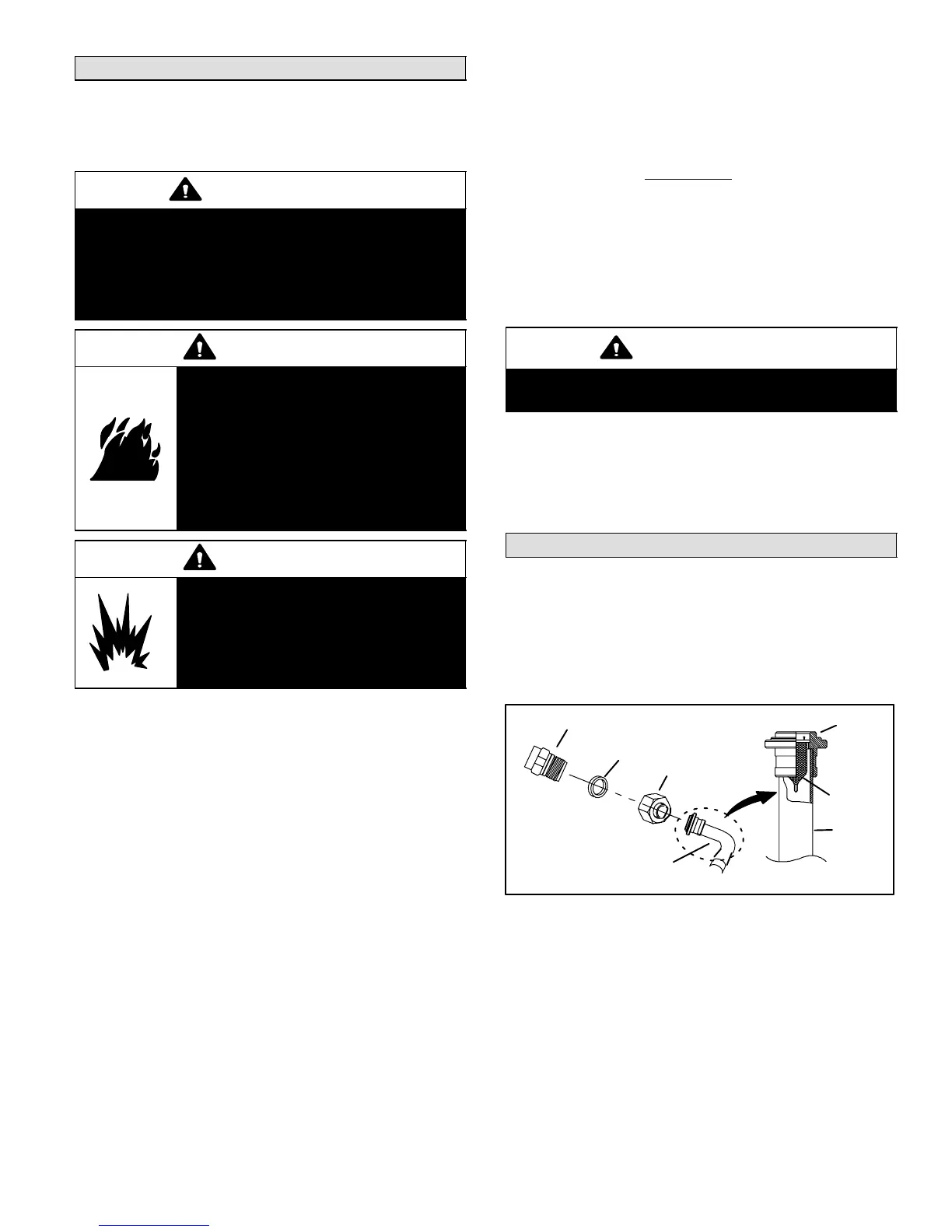
REPLACEMENT PARTS
If replacement parts are necessary for the indoor unit,
order kit 69J46 (LB−95325A). The kit includes:
TEFLON RINGS (20)
BRASS NUTS (10)
LIQUID LINE ASSEMBLIES
(INCLUDES STRAINER) (10)
LIQUID LINE ORIFICE HOUSINGS (10)
LIQUID LINE
ASSEMBLY
COPPER
TUBE
PISTON
RETAINER
STRAINER
Figure 19. 69J46 Kit Components

 Loading...