Page 9
XC14 SERIES
New or Replacement Line Set
This section provides information on installation or
replacement of existing line set. If line set are not being
installed then proceed to Brazing Connections on page 11.
If refrigerant lines are routed through a wall, seal and
isolate the opening so vibration is not transmitted to the
building. Pay close attention to line set isolation during
installation of any HVAC system. When properly isolated
from building structures (walls, ceilings. floors), the
refrigerant lines will not create unnecessary vibration and
subsequent sounds. Also, consider the following when
placing and installing a high−efficiency air conditioner.
REFRIGERANT LINE SET
Field refrigerant piping consists of liquid and suction lines
from the outdoor unit (braze connections) to the indoor unit
coil (flare or sweat connections). Use Lennox L15 (sweat,
non−flare) series line set, or use field−fabricated refrigerant
lines as listed in table 2.
Table 2. Refrigerant Line Set
Model
Field Connections Recommended Line Set
Liquid
Line
Suction
Line
Liquid
Line
Suction
Line
L15 Line Set
−018
−024
−030
3/8".
(10 mm)
3/4"
(19 mm)
3/8"
(10 mm)
3/4"
(19 mm)
L15−41
15 ft. − 50 ft.
(4.6 m − 15 m)
−036
−042
−048
3/8".
(10 mm)
7/8"
(22 mm)
3/8"
(10 mm)
7/8"
(22 mm)
L15−65
15 ft. − 50 ft.
(4.6 m − 15 m)
−060
3/8".
(10 mm)
1−1/8".
(29 mm)
3/8"
(10 mm)
1−1/8"
(29 mm)
Field
Fabricated
NOTE − When installing refrigerant lines longer than 50
feet, see the Lennox Refrigerant Piping Design and
Fabrication Guidelines, or contact Lennox Technical
Support Product Applications for assistance. To obtain the
correct information from Lennox, be sure to communicate
the following points:
Model (XC14) and size of unit (e.g. −060).
Line set diameters for the unit being installed as listed
in table 2 and total length of installation.
Number of elbows and if there is a rise or drop of the
piping.
MATCHING WITH NEW OR EXISTING INDOOR COIL
AND LINE SET
The RFC1−metering line consisted of a small bore copper
line that ran from condenser to evaporator coil. Refrigerant
was metered into the evaporator by utilizing
temperature/pressure evaporation effects on refrigerant in
the small RFC line. The length and bore of the RFC line
corresponded to the size of cooling unit.
If the XC14 is being used with either a new or existing
indoor coil which is equipped with a liquid line which served
as a metering device (RFCI), the liquid line must be
replaced prior to the installation of the XC14 unit. Typically
a liquid line used to meter flow is 1/4" in diameter and
copper.
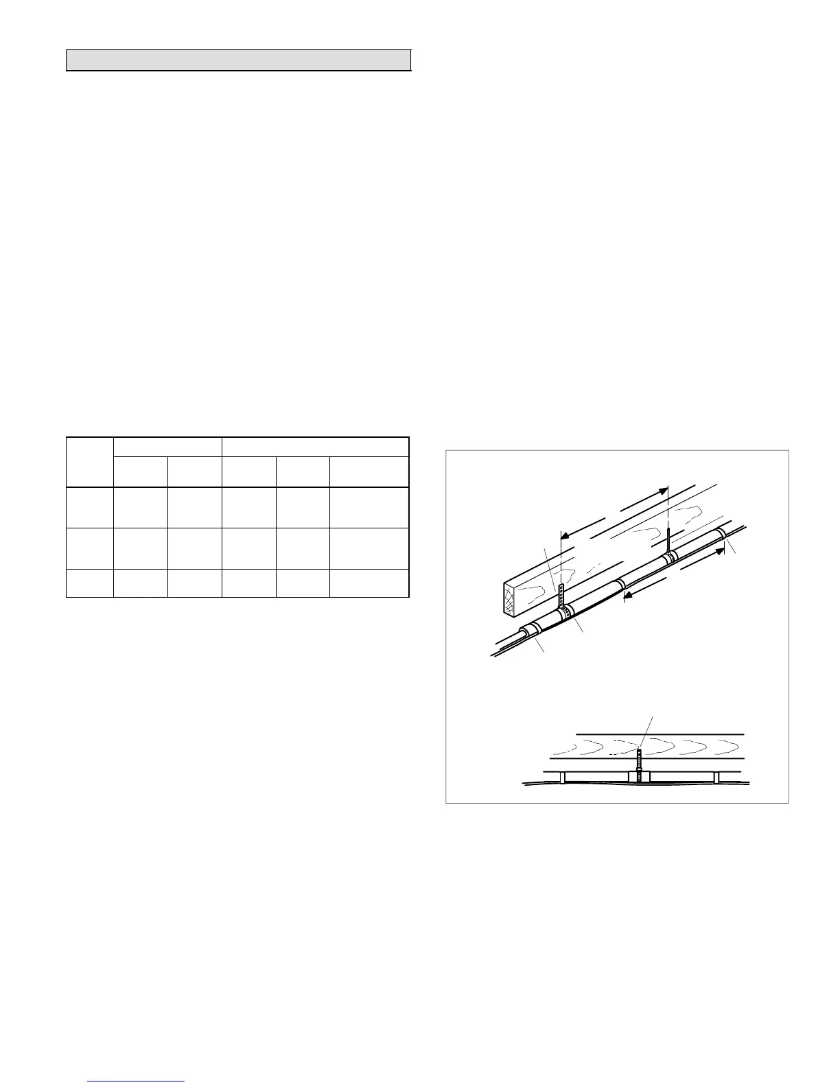
INSTALLING LINE SET
Line Set IsolationThis reference illustrates
procedures, which ensure proper refrigerant line set
isolation:
Installation of line set on horizontal runs is
illustrated in figure 15.
Installation of a transition from horizontal to
vertical is illustrated in figure 17.
Installation of line set on vertical runs is illustrated in
figure 16.
METAL
SLEEVE
STRAPPING MATERIAL
(AROUND SUCTION
LINE ONLY)
TAPE OR
WIRE TIE
WIRE TIE (AROUND
SUCTION LINE ONLY)
FLOOR JOIST OR
ROOF RAFTER
TAPE OR
WIRE TIE
TO HANG LINE SET FROM JOIST OR
RAFTER, USE EITHER METAL STRAPPING
MATERIAL OR ANCHORED HEAVY NYLON
WIRE TIES.
8 FEET
8 FEET
STRAP THE SUCTION LINE TO
THE JOIST OR RAFTER AT 8 FEET
INTERVALS THEN STRAP THE
LIQUID LINE TO THE SUCTION
LINE.
FLOOR JOIST OR
ROOF RAFTER
Figure 15. Refrigerant Line Set: Installing
Horizontal Runs

 Loading...