Page 16
505367M 04/08
NOTE − Normally, the high pressure hose is connected to
the liquid line port; however, connecting it to the suction
port better protects the manifold gauge set from high
pressure damage.
2. With both manifold valves closed, connect the cylinder
of HFC−410A refrigerant to the center port of the
manifold gauge set. Open the valve on the HFC−410A
cylinder (suction only).
3. Open the high pressure side of the manifold to allow
HFC−410A into the line set and indoor unit. Weigh in
a trace amount of HFC−410A. [A trace amount is a
maximum of two ounces (57 g) refrigerant or three
pounds (31 kPa) pressure]. Close the valve on the
HFC−410A cylinder and the valve on the high pressure
side of the manifold gauge set. Disconnect the
HFC−410A cylinder.
4. Connect a cylinder of dry nitrogen with a pressure
regulating valve to the center port of the manifold
gauge set.
5. Adjust dry nitrogen pressure to 150 psig (1034 kPa).
Open the valve on the high side of the manifold gauge
set in order to pressurize the line set and the indoor unit.
6. After a few minutes, open one of the service valve
ports and verify that the refrigerant added to the
system earlier is measurable with a leak detector.
NOTE − Amounts of refrigerant will vary with line lengths.
7. Check all joints for leaks.
8. Purge dry nitrogen and HFC−410A mixture.
9. Correct any leaks and recheck.
10. After leak testing disconnect gauges from service
ports.
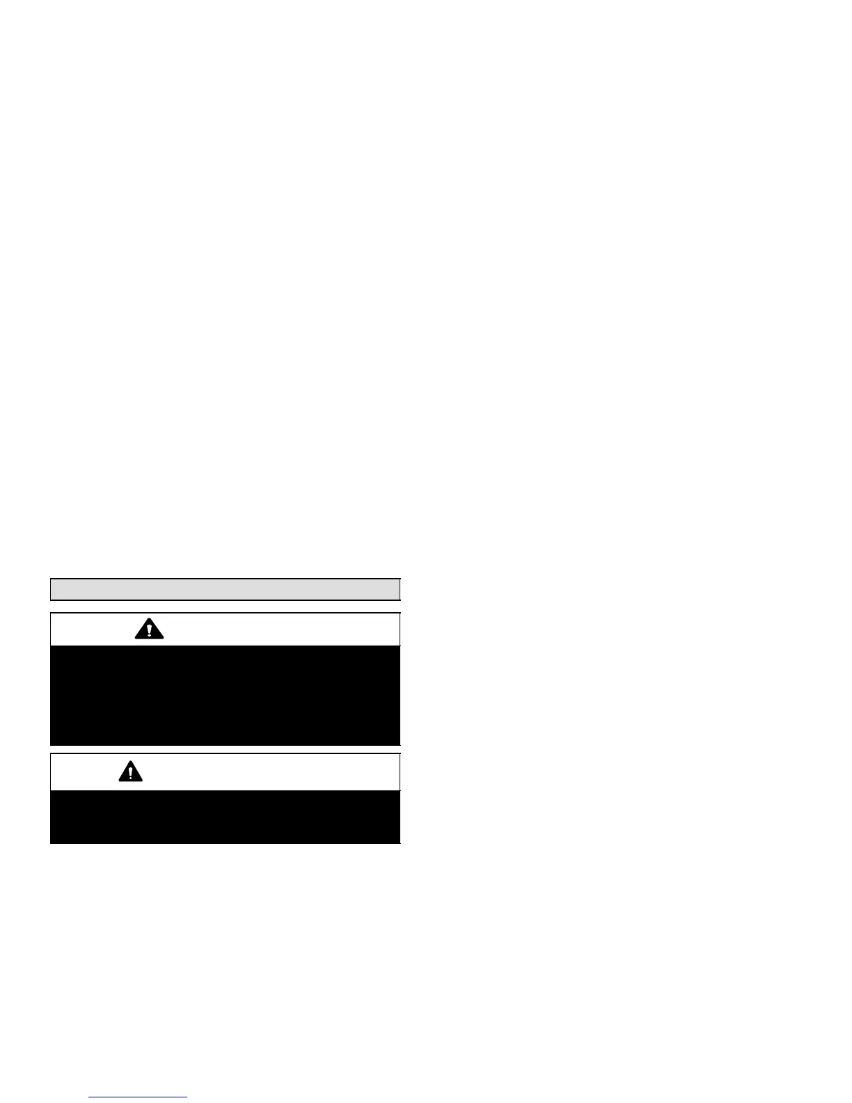
Evacuating the System
WARNING
Danger of Equipment Damage. Avoid deep
vacuum operation. Do not use compressors to
evacuate a system. Extremely low vacuums can
cause internal arcing and compressor failure.
Damage caused by deep vacuum operation will
void warranty.
IMPORTANT
Use a thermocouple or thermistor electronic vacuum
gauge that is calibrated in microns. Use an instrument
capable of accurately measuring down to 50 microns.
Evacuating the system of non−condensables is critical for
proper operation of the unit. Non−condensables are
defined as any gas that will not condense under
temperatures and pressures present during operation of
an air conditioning system. Non−condensables and water
suction combine with refrigerant to produce substances
that corrode copper piping and compressor parts.
NOTE − Remove cores from service valves if not already
done.
1. Connect manifold gauge set to the service valve ports
as follows:
low pressure gauge to suction line service valve
high pressure gauge to liquid line service valve
2. Connect micron gauge.
3. Connect the vacuum pump (with vacuum gauge) to
the center port of the manifold gauge set.
4. Open both manifold valves and start the vacuum
pump.
5. Evacuate the line set and indoor unit to an absolute
pressure of 23,000 microns (29.01 inches of
mercury).
NOTE − During the early stages of evacuation, it is
desirable to close the manifold gauge valve at least once to
determine if there is a rapid rise in pressure this indicates a
relatively large leak. If this occurs, repeat the leak testing
procedure.
NOTE − The term absolute pressure means the total
actual pressure within a given volume or system, above
the absolute zero of pressure. Absolute pressure in a
vacuum is equal to atmospheric pressure minus vacuum
pressure.
6. When the absolute pressure reaches 23,000 microns
(29.01 inches of mercury), close the manifold gauge
valves, turn off the vacuum pump and disconnect the
manifold gauge center port hose from vacuum pump.
Attach the manifold center port hose to a dry nitrogen
cylinder with pressure regulator set to 150 psig (1034
kPa) and purge the hose. Open the manifold gauge
valves to break the vacuum in the line set and indoor
unit. Close the manifold gauge valves.
7. Shut off the dry nitrogen cylinder and remove the
manifold gauge hose from the cylinder. Open the
manifold gauge valves to release dry nitrogen from the
line set and indoor unit.
8. Reconnect the manifold gauge to vacuum pump, turn
pump on, and continue to evacuate line set and indoor
unit until the absolute pressure does not rise above
500 microns (29.9 inches of mercury) within a
20−minute period after shutting off vacuum pump and
closing the manifold gauge valves.
9. When the absolute pressure requirement above has
been met, disconnect the manifold hose from the
vacuum pump and connect it to an upright cylinder of
HFC−410A refrigerant. Open the manifold gauge valve
pressure line set to break vacuum with 2 to 5 psi.
10. Perform the following:
A Close manifold gauge valves
B Shut off HFC−410A cylinder
C Reinstall service valve cores by removing
manifold hose from service valve. Quickly install
core with core tool while maintaining a positive
system pressure.
D Replace the stem caps and secure finger tight,
then tighten an additional one−sixth (1/6) of a turn
as illustrated in figure 1.

 Loading...