Page 5
B − Two−Stage Scroll Compressor (B1)
CAUTION
In order to avoid injury, take precaution when
lifting heavy objects.
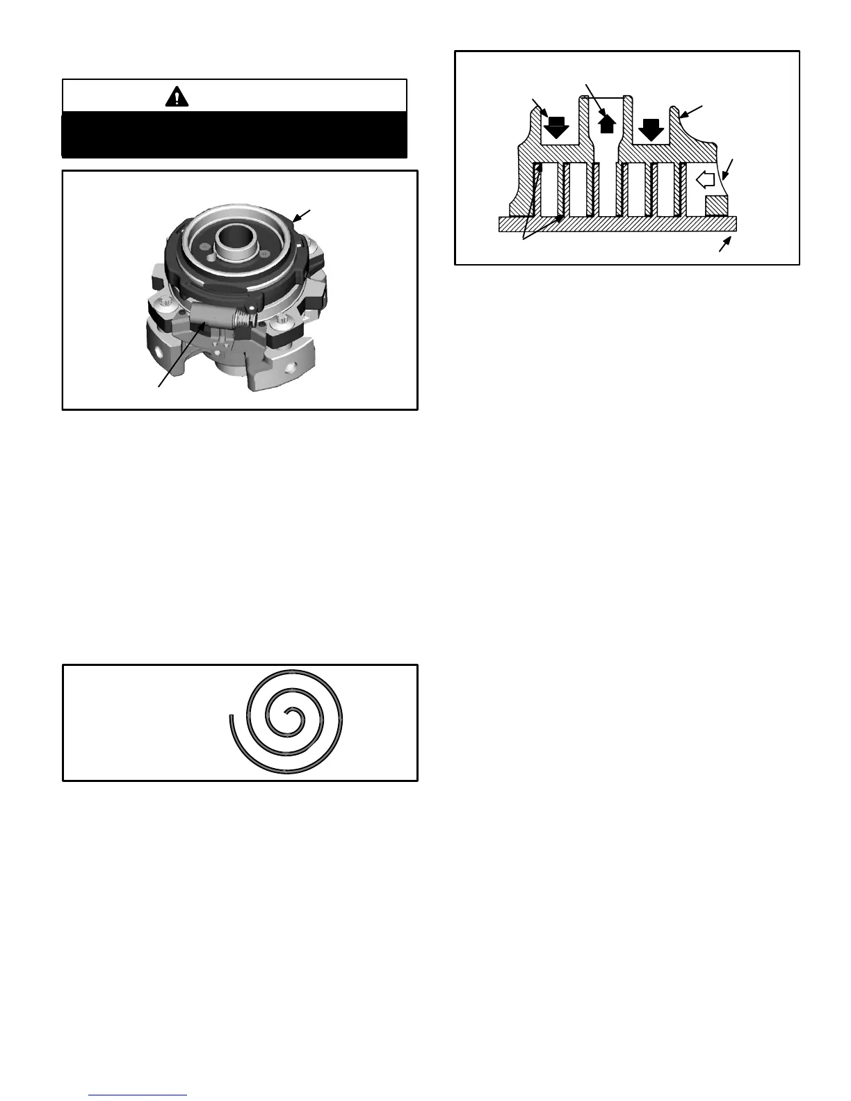
FIGURE 1
TWO−STAGE MODULATED SCROLL
solenoid actuator coil
slider ring
The scroll compressor design is simple, efficient and re-
quires few moving parts. A cutaway diagram of the scroll
compressor is shown in figure 1.The scrolls are located in
the top of the compressor can and the motor is located just
below. The oil level is immediately below the motor.
The scroll is a simple compression concept centered around
the unique spiral shape of the scroll and its inherent proper-
ties. Figure 2 shows the basic scroll form. Two identical
scrolls are mated together forming concentric spiral shapes
(figure 3 ). One scroll remains stationary, while the other is
allowed to orbit" (figure 4). Note that the orbiting scroll does
not rotate or turn but merely orbits" the stationary scroll.
FIGURE 2
SCROLL FORM
FIGURE 3
STATIONARY
SCROLL
ORBITING SCROLL
DISCHARGE
SUCTION
CROSS−SECTION OF SCROLLS
TIPS SEALED BY
DISCHARGE PRESSURE
DISCHARGE
PRESSURE
The counterclockwise orbiting scroll draws gas into the outer
crescent shaped gas pocket created by the two scrolls (figure
4 − 1). The centrifugal action of the orbiting scroll seals off the
flanks of the scrolls (figure 4 − 2). As the orbiting motion con-
tinues, the gas is forced toward the center of the scroll and the
gas pocket becomes compressed (figure 4 −3). When the
compressed gas reaches the center, it is discharged vertical-
ly into a chamber and discharge port in the top of the com-
pressor (figure1). The discharge pressure forcing down on
the top scroll helps seal off the upper and lower edges (tips) of
the scrolls (figure 3 ). During a single orbit, several pockets of
gas are compressed simultaneously providing smooth con-
tinuous compression.
The scroll compressor is tolerant to the effects of liquid re-
turn. If liquid enters the scrolls, the orbiting scroll is allowed
to separate from the stationary scroll. The liquid is worked
toward the center of the scroll and is discharged. If the com-
pressor is replaced, conventional Lennox cleanup practices
must be used.
Due to its efficiency, the scroll compressor is capable of
drawing a much deeper vacuum than reciprocating com-
pressors. Deep vacuum operation can cause internal fusite
arcing resulting in damaged internal parts and will result in
compressor failure. This type of damage can be detected
and will result in denial of warranty claims. The scroll com-
pressor can be used to pump down refrigerant as long as
the pressure is not reduced below 7 psig.
The scroll compressors in all XC16 model units are de-
signed for use with R410A refrigerant and operation at high
pressures. Compressors are shipped from the factory with
3MA (32MMMA) P.O.E. oil. See electrical section in this
manual for compressor specifications.
NOTE − During operation, the head of a scroll compressor
may be hot since it is in constant contact with discharge
gas.
 Loading...