Page 49
XP17
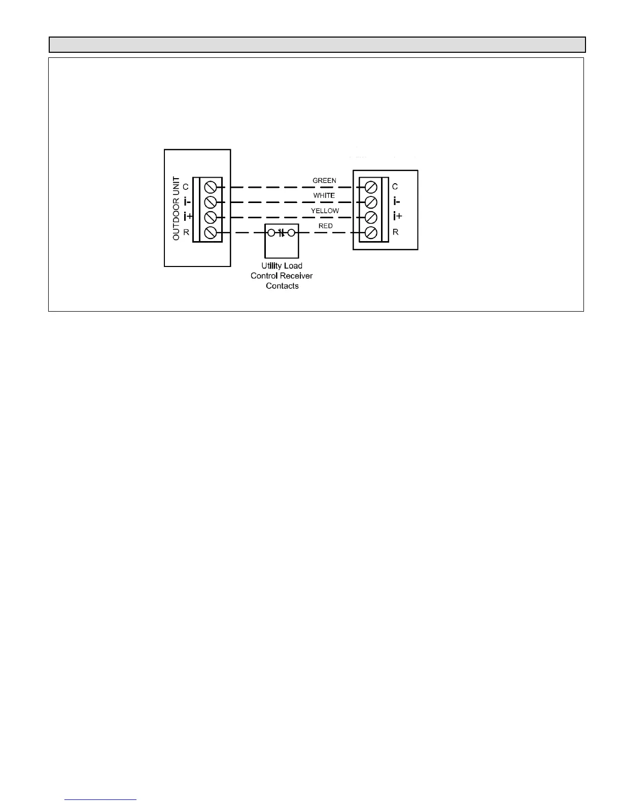
Load Shed Wiring
XC21 iComfort™ Outdoor Unit
Wiring Detail with Utility Load Shedding - Preferred Wiring Method
iComfort™ Furnace or
Air Handler
iComfort™ Air Conditioning
or Heat Pump Outdoor Unit
Outdoor Control
Part Numbers
101796-xx
101797-xx
101798-xx
101799-xx
103369-01
103369-02
Figure 26. Preferred Method - Outdoor Controls - 101796-xx, 101797-xx, 101798-xx, 101799-xx, 103369-01 and
103369-02)
Information in this note shows the proper application and
interface wiring of utility load control devices to Lennox
iComfort™-enabled outdoor units installed on
iComfort™-enabled communicating thermostat systems.
PREFERRED WIRING (OUTDOOR CONTROLS -
101796-XX, 101797-XX, 101798-XX, 101799-XX,
103369-01 AND 103369-02)
1. Utility Load Shedding Mode ACTIVATED (Utility
Cycled Unit OFF) – The normally closed set of
contacts in the utility load control receiver open. This
interrupts the R iComfort™ communication wire
between the indoor unit and iComfort™-enabled
outdoor unit. The iComfort™-enabled outdoor unit will
be cycled OFF. A "Lost Communication alert" will
appear on the display of the iComfort WiFi
®
thermostat. If the customer has selected the option to
be notified when an alert occurs, the customer will be
notified by email when the alert occurs.
2. Utility Load Shedding Mode DEACTIVATED
(Normal Equipment Operation) – When load
shedding is deactivated, the contacts in the utility load
control receiver are closed. The R iComfort™
communication wire between the indoor unit and
iComfort™ outdoor unit is connected and iComfort™
communication is restored. The outdoor unit will return
to normal operation and the alert code will clear.
PREFERRED WIRING (OUTDOOR CONTROL -
103369-03)
1. Utility Load Shedding Mode ACTIVATED (Utility
Cycled Unit OFF) – The normally closed set of
contacts in the utility load control receiver “open”. This
removes 24VAC from the coil of the field-provided
relay (catalog # 69J79). The relay contacts close
(terminal 7 to terminal 2), completing the circuit
between terminals R and L on the outdoor control. This
24VAC input to terminal L activates the load shedding
mode in the outdoor control and the outdoor unit will be
cycled OFF. The 7‐Segment display on the outdoor
control will display a load shedding alert code E600
and an alert will appear on the display of the iComfort
WiFi
®
thermostat. If the customer has selected the
option to be notified when an alert occurs, the
customer will be notified by email when the alert
occurs.
2. Utility Load Shedding Mode DEACTIVATED
(Normal Equipment Operation) – When load
shedding not required, the contacts in the utility load
control receiver are closed. This provides 24VAC to the
coil of the field provided relay (catalog # 69J79).The
relay contacts OPEN (terminal 7 to terminal 2)
removing 24VAC from the L terminal on the outdoor
control. This deactivates the load shedding mode in
the outdoor control. The outdoor unit will return to
normal operation and alert code will clear.
 Loading...