06/11 506601−01
*2P0611* *P506601-01*
Page 1
E20 Lennox Industries Inc.
Dallas, Texas, USA
RETAIN THESE INSTRUCTIONS
FOR FUTURE REFERENCE
These instructions are intended as a general guide and do
not supersede local codes in any way. Consult authorities
having jurisdiction before installation.
NOTICE TO INSTALLER
It is critical for proper defrost operation to set the defrost termination
pins (E47) on the heat pump control prior to starting system. See
Defrost System section on page 33 for further details.
DEFROST OPERATION
UNIT PLACEMENT
It is critical for proper unit operation to place outdoor unit on an
elevated surface as described in Unit Placement section on page 7.
BRAZING LINE SET TO SERVICE VALVES
It is imperative to follow the brazing technique illustrated starting on
page 13 to avoid damaging the service valve’s internal seals.
NOTICE
A thermostat is not included and must be ordered
separately.
D The Lennox icomfort Touch
®
thermostat must be used
in communicating application
D In non−icomfortt applications, the Lennox
ComfortSense
®
7000 thermostat may be used, as well
as other non−communicating thermostats.
In all cases, setup is critical to ensure proper system
operation.
Field wiring examples for non−icomforttapplications
begin on page 25.
See the icomfort Touch
®
thermostat Quick Start Guide
for communicating and partial communicating field
wiring connections.
INSTALLATION
INSTRUCTIONS
Dave Lennox Signature
®
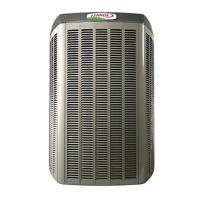
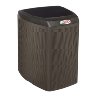
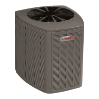
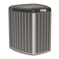
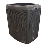
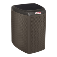
Collection XP21 System
HEAT PUMPS
506601−01
06/11
Supersedes 05/11
TABLE OF CONTENTS
General 1. . . . . . . . . . . . . . . . . . . . . . . . . . . . . . . . . . . . . .
Unit Dimensions 2. . . . . . . . . . . . . . . . . . . . . . . . . . . . . . .
Model Number Identification 2. . . . . . . . . . . . . . . . . . . .
Typical Unit Parts Arrangement 3. . . . . . . . . . . . . . . . .
Shipping and Packing List 4. . . . . . . . . . . . . . . . . . . . . .
Using Manifold Gauge Set 4. . . . . . . . . . . . . . . . . . . . . .
Operating Service Valves 4. . . . . . . . . . . . . . . . . . . . . . .
Recovering Refrigerant from Existing System 6. . . . .
Unit Placement 7. . . . . . . . . . . . . . . . . . . . . . . . . . . . . . . .
Removing and Installing Panels 9. . . . . . . . . . . . . . . . .
New or Replacement Line Set 11. . . . . . . . . . . . . . . . . . .
Brazing Connections 13. . . . . . . . . . . . . . . . . . . . . . . . . . .
Flushing Line Set and Indoor Coil 16. . . . . . . . . . . . . . . .
Installing Indoor Expansion Valve 17. . . . . . . . . . . . . . . .
Leak Test Line Set and Indoor Coil 18. . . . . . . . . . . . . . .
Evacuating Line Set and Indoor Coil 18. . . . . . . . . . . . .
Electrical 20. . . . . . . . . . . . . . . . . . . . . . . . . . . . . . . . . . . . .
Heat Pump Control (A175) Jumpers and Terminals 23
Field Control Wiring 25. . . . . . . . . . . . . . . . . . . . . . . . . . . .
Servicing Unit Delivered Void of Charge 27. . . . . . . . . .
Unit Start−Up 27. . . . . . . . . . . . . . . . . . . . . . . . . . . . . . . . . .
System Refrigerant 27. . . . . . . . . . . . . . . . . . . . . . . . . . . .
Air Handler / Coil Match up and Targeted
Subcooling Values 30. . . . . . . . . . . . . . . . . . . . . . . . . . . . .
Operating and Temperature Pressures 31. . . . . . . . . . .
System Operations 32. . . . . . . . . . . . . . . . . . . . . . . . . . . .
Defrost System 33. . . . . . . . . . . . . . . . . . . . . . . . . . . . . . .
System Status, Fault and Lockout LED Codes 43. . . . .
Field Component Configuration and Testing 48. . . . . . .
Maintenance (Dealer and Homeowner) 55. . . . . . . . . . .
SunSource
®
Home Energy System 57. . . . . . . . . . . . . .
Checklists 57. . . . . . . . . . . . . . . . . . . . . . . . . . . . . . . . . . . .
General
This outdoor unit is designed for use with HFC−410A
refrigerant only. This unit must be installed with an
approved indoor air handler or coil. See the Lennox XP21
Engineering Handbook for approved indoor component
match ups.
Litho U.S.A.
