Page 25
XP21 SERIES
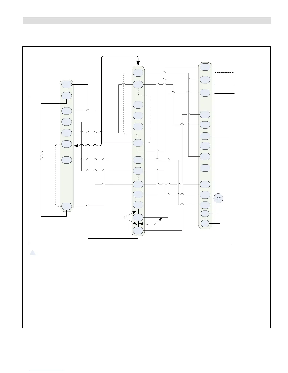
Field Control Wiring
The following two illustrations provide examples on how to install control wiring using a non−communicating thermostat. For
examples of how to install control wiring in complete or partial communicating systems, see the icomfort Touch
®
thermostat
Quick Start Guide which is provided with the thermostat.
Y1
O
R
W1
G
D
R
Y1
L
C
C
B
Y2
Y2
W
O
DS
L
T
T
W2
H
W3
H
O
C
L
Y2
DS
DH
G
R
Y1
W2
W1
1
2
5
6
8
7
On−board link
Low voltage
thermostat wiring
Flat metal jumper
3
4
1. Thermostat T terminals are used for outdoor sensor input. Use for thermostat’s outdoor temperature display (optional).
2. R to L connection is required for this model when using the ComfortSense
®
7000 − catalog number Y0349 only. Resistor Kit (catalog number 47W97)
required and ordered separately.
3. Air handler control ships from factory with metal jumpers installed across W1, W2 and W3. For one−stage electric heat, do not remove factory installed
metal jumpers.
4. Air handler control ships from factory with metal jumpers installed across W1, W2 and W3. For two−stage electric heat, remove factory installed metal
jumper between W1 to W2. Then connect thermostat wire between the air handler control’s W2 and the thermostat’s W2 terminal.
5. Cut on−board link (clippable wire) from R−O HEAT PUMP for heat pump applications.
6. Cut on−board link (clippable wire) from Y1−Y2 2 STAGE COMPR for two−stage compressor and two−speed fan operation.
7. Cut loop jumper (clippable wire) DS to R on two−stage units for Humiditrol
®
whole−home dehumidication system applications. This will slow the
outdoor unit’s fan speed to a specific RPM. A wire must be installed between the DS terminals on the furnace and outdoor unit controls. See table
15 for fan speed based on unit capacity.
8. Cut on−board link (clippable wire) DS−R for Humiditrol
®
whole−home dehumidication system or Harmony IIIt zoning system applications. This will
slow the indoor blower motor to the lowest speed setting. See furnace installation instruction or engineering handbook for lowest fan speed
information.
HEAT PUMP
CONTROL (A175)
AIR HANDLER
CONTROL
INDOOR
THERMOSTAT (S1)
Figure 17. ComfortSense® 7000 Series Thermostat Air Hander/Two−Stage Heat Pump
 Loading...