Page 23
XP21 SERIES
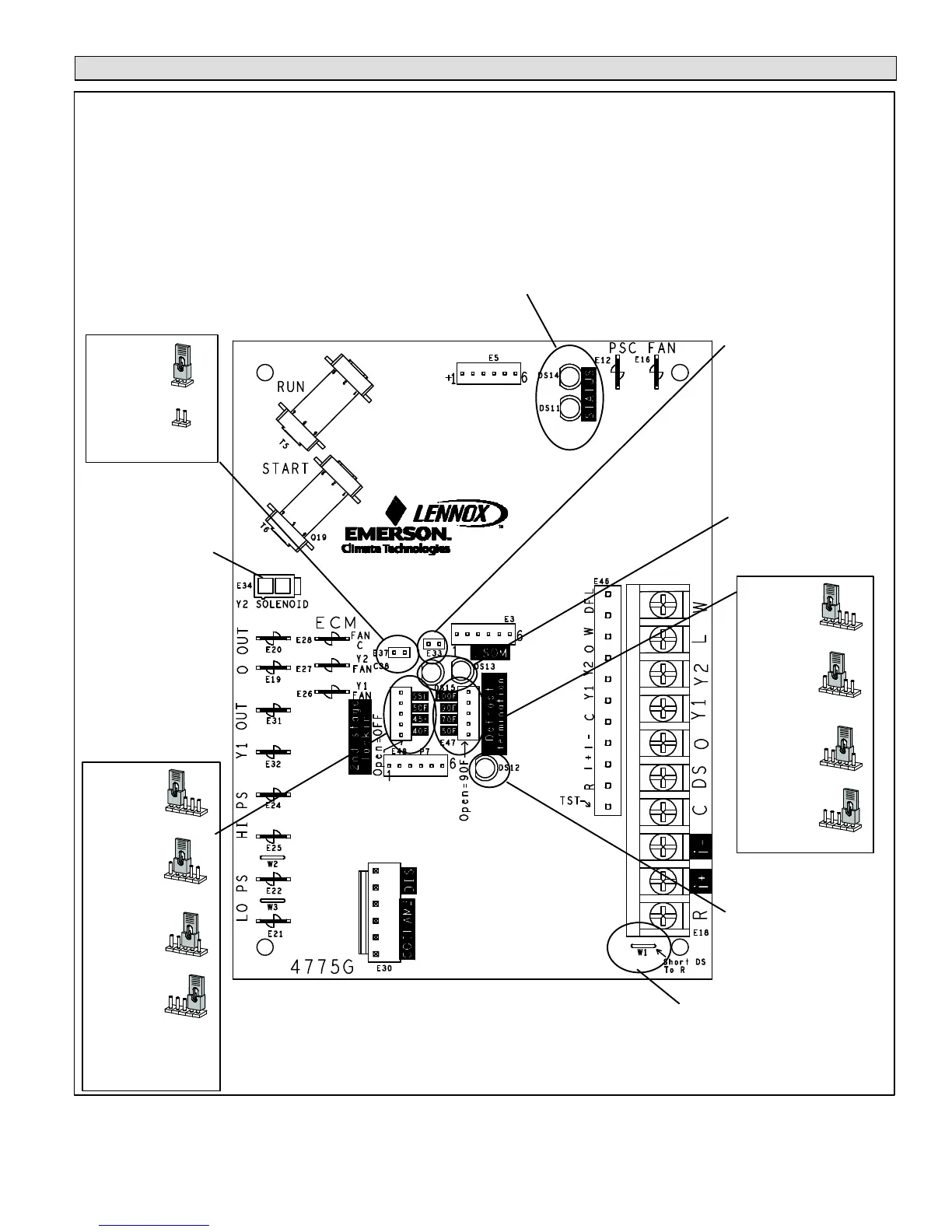
Heat Pump Control (A175) Jumpers and Terminals
55
50
DEGREE
TARGET
45
DEGREE
TARGET
40
DEGREE
TARGET
55
50
45
40
SECOND−STAGE LOCK−IN TEMPERATURE
55
50
45
40
55
50
45
40
55
50
45
40
DEGREE
TARGET
100
90
DEGREE
TARGET
70
DEGREE
TARGET
*50
DEGREE
TARGET
100
90
70
50
DEGREE
TARGET
DEFROST TERMINATION TEMPERATURE
100
90
70
50
100
90
70
50
100
90
70
50
30
0
COMPRESSOR SHIFT DELAY
*30
SECOND DELAY
SECOND DELAY
0
LED ALERT CODES
LED ALERT CODES
INDICATES RS−BUS DATA
COMMUNICATION IS ACTIVE.
(COMMUNICATION MODE
ONLY)
Table 3 on page 24 provides additional information concerning jumpers, links, and connections for the heat pump control.
E37
E47
DS12
E48
E34
DS11 and DS14
DS13 and DS15
JUMPER REMOVED − NO SECOND STAGE LOCK−IN TEMPERATURE.
E33
TEST PINS (SEE
FIGURE 28 FOR
DESCRIPTION OF
VARIOUS FUNCTIONS)
HEAT PUMP CONTROL TWO STAGE
CUT FOR HUMIDITROL APPLICATION
(TWO−STAGE UNITS ONLY)
W1
*NO JUMPER
NOTE Earlier produce units will have a default factory setting (jumper
present) for 40ºF. Later produce units will have no jumper by default present
on E48.
Figure 16. Heat Pump Control Connections, Jumper Settings and LED Locations
 Loading...