Page 32
506601−01
Table 9. HFC−410A Temperature (°F) − Pressure (Psig)
°F Psig °F Psig °F Psig °F Psig °F Psig °F Psig °F Psig °F Psig
32 100.8 48 137.1 63 178.5 79 231.6 94 290.8 110 365.0
125 445.9
141 545.6
33 102.9 49 139.6 64 181.6 80 235.3 95 295.1 111 370.0 126 451.8 142 552.3
34 105.0 50 142.2 65 184.3 81 239.0 96 299.4 112 375.1 127 457.6 143 559.1
35 107.1 51 144.8 66 187.7 82 242.7 97 303.8 113 380.2 128 463.5 144 565.9
36 109.2 52 147.4 67 190.9 83 246.5 98 308.2 114 385.4 129 469.5 145 572.8
37 111.4 53 150.1 68 194.1 84 250.3 99 312.7 115 390.7 130 475.6 146 579.8
38 113.6 54 152.8 69 197.3 85 254.1 100 317.2 116 396.0 131 481.6 147 586.8
39 115.8 55 155.5 70 200.6 86 258.0 101 321.8 117 401.3 132 487.8 148 593.8
40 118.0 56 158.2 71 203.9 87 262.0 102 326.4 118 406.7 133 494.0 149 601.0
41 120.3 57 161.0 72 207.2 88 266.0 103 331.0 119 412.2 134 500.2 150 608.1
42 122.6 58 163.9 73 210.6 89 270.0 104 335.7 120 417.7 135 506.5 151 615.4
43 125.0 59 166.7 74 214.0 90 274.1 105 340.5 121 423.2 136 512.9 152 622.7
44 127.3 60 169.6 75 217.4 91 278.2 106 345.3 122 428.8 137 519.3 153 630.1
45 129.7 61 172.6 76 220.9 92 282.3 107 350.1 123 434.5 138 525.8 154 637.5
46 132.2 62 175.4 77 224.4 93 286.5 108 355.0 124 440.2 139 532.4 155 645.0
47 134.6 78 228.0 109 360.0 140 539.0
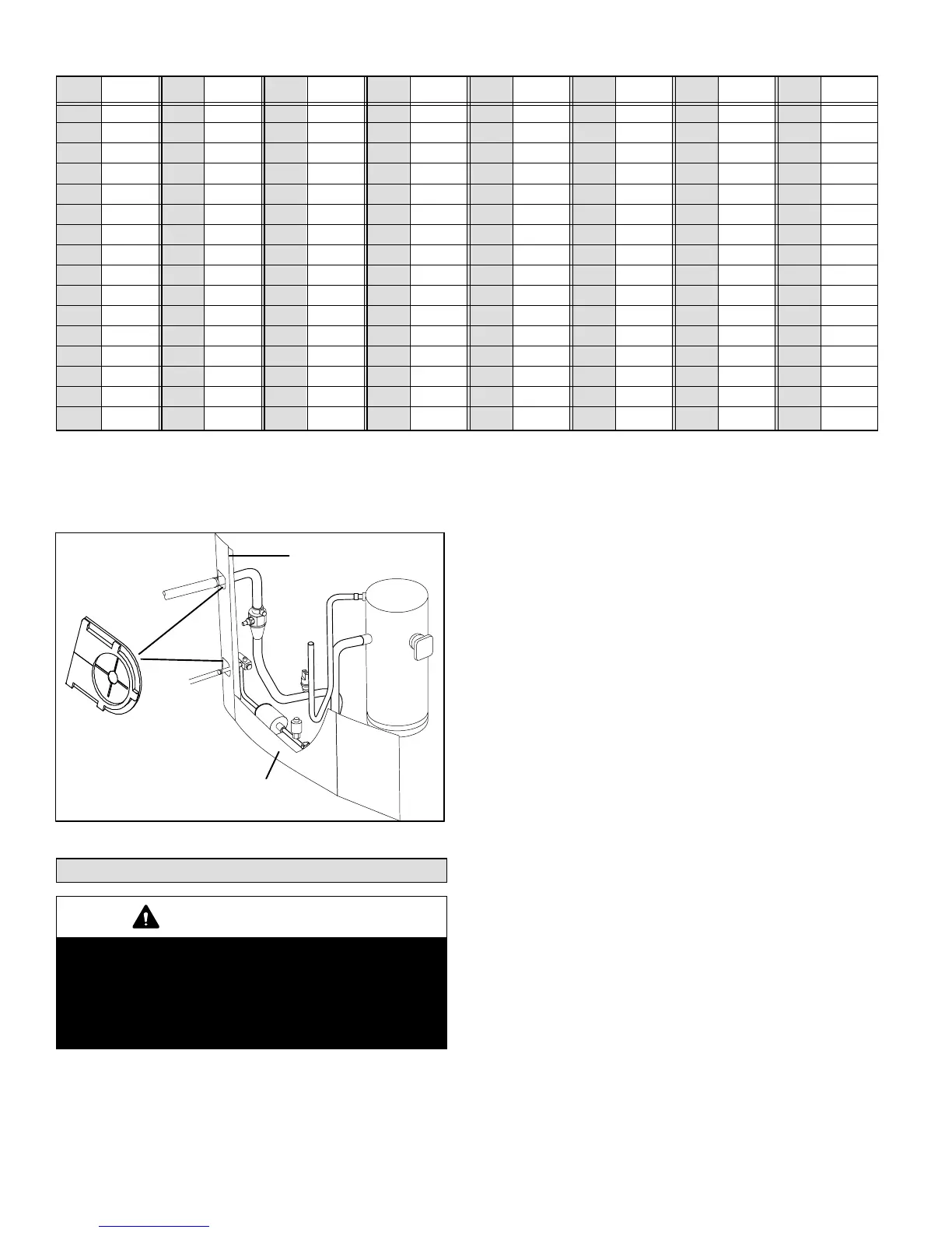
INSTALLING ISOLATION GROMMETS
Locate the isolation grommets (provided). Slide grommets
onto vapor and liquid lines. Insert grommets into piping
panel to isolate refrigerant lines from sheet metal edges.
TWO ISOLATION GROMMETS ARE
PROVIDE FOR THE LIQUID AND
SUCTION LINE PIPE PANEL PASS
THROUGH.
LIQUID LINE
SUCTION LINE
REAR VIEW OF UNIT EXTERIOR
PIPING PANEL
Figure 23. Isolation Grommets
System Operations
IMPORTANT
Some scroll compressor have internal vacuum protector
that will unload scrolls when suction pressure goes
below 20 psig. A hissing sound will be heard when the
compressor is running unloaded. Protector will reset
when low pressure in system is raised above 40 psig. DO
NOT REPLACE COMPRESSOR.
The heat pump control (A175) provides the following
functions:
S Demand defrost algorithm
S Field−selectable defrost termination temperatures
S Internal switching of outputs
S Compressor anti−short−cycle delay.
S Five−strikes lockout safety function
S High (S4) and low (S87) pressure switches
S Ambient (RT13), coil (RT21) and discharge line
(RT28) temperatures monitoring and protection.
COMPRESSOR PROTECTION ANTI−SHORT
CYCLE DELAY
The heat pump control protects the compressor from:
S Short cycling (five minutes) when there is initial power
up
S Interruption in power to the unit
S Pressure or sensor trips
S Delay after Y1 demand is removed.
In non−communicating systems the delay is set for 300
seconds (five minutes) and can not be changed. To
override timer when active or inactive, place a jumper on
the field test pins between 1 and 2 seconds.
In communicating system, the icomfort Touch
®
thermostat
has a separate built−in 5−minute non−adjustable short cycle
protection.
 Loading...