EasyManua.ls Logo

Lennox XP21 Series User Manual

Lennox XP21 Series
83 pages
To Next Page IconTo Next Page
To Previous Page IconTo Previous Page
Page #58 background imageLoading...
Page #58 background image
Page 58
XP17
STABILIZING UNIT ON UNEVEN SURFACES
IMPORTANT
Unit Stabilizer Bracket Use (field-provided):
Always use stabilizers when unit is raised above the
factory height. (Elevated units could become unstable in
gusty wind conditions).
Stabilizers may be used on factory height units when
mounted on unstable an uneven surface.
With unit positioned at installation site, perform the
following
:
1. Remove two side louvered panels to expose the unit
base.
2. Install the brackets as illustrated in figure 36, detail D
using conventional practices.
3. Replace the panels after installation is complete.
ROOF MOUNTING
Install the unit a minimum of 6 inches (152 mm) above the
roof surface to avoid ice build-up around the unit. Locate
the unit above a load bearing wall or area of the roof that
can adequately support the unit. Consult local codes for
rooftop applications.
If unit coil cannot be mounted away from prevailing winter
winds, a wind barrier should be constructed. Size barrier at
least the same height and width as outdoor unit. Mount
barrier 24 inches (610 mm) from the sides of the unit in the
direction of prevailing winds.
NOTICE
Roof Damage!
This system contains both refrigerant and oil. Some
rubber roofing material may absorbed oil and cause the
rubber to swell when it comes into contact with oil. The
rubber will then bubble and could cause leaks. Protect
the roof surface to avoid exposure to refrigerant and oil
during service and installation. Failure to follow this
notice could result in damage to roof surface.
WIND BARRIER
PREVAILING WINTER
WINDS
INLET AIR
INLET AIR
INLET AIR
24 (610)
Figure 35. Rooftop Application and Wind Barrier —
Inches (Millimeters)

Other manuals for Lennox XP21 Series

Question and Answer IconNeed help?

Do you have a question about the Lennox XP21 Series and is the answer not in the manual?

Lennox XP21 Series Specifications

General IconGeneral
TypeHeat Pump
RefrigerantR-410A
SEER Rating21
Cooling Capacity2-5 tons
Heating Capacity2-5 tons
Warranty10-Year Limited Warranty on compressor and covered components

Summary

Overview

Model Number Identification

Explains how to identify model numbers based on code.

Specifications

Lists unit specifications, including sound rating and refrigerant charge.

Electrical Data

Provides electrical specifications for compressor and condenser fan components.

System Operation and Service

Jumpers, Loops and Terminals

Details jumpers, loops, and terminals on the heat pump control board.

Compressor Protection Features

Covers anti-short delay, pressure switches, and 5-strike lockout for compressor.

System Status, Fault and Lockout LED Codes

Explains LED codes for system status, faults, and lockouts on the control board.

Installation

Unit Placement Considerations

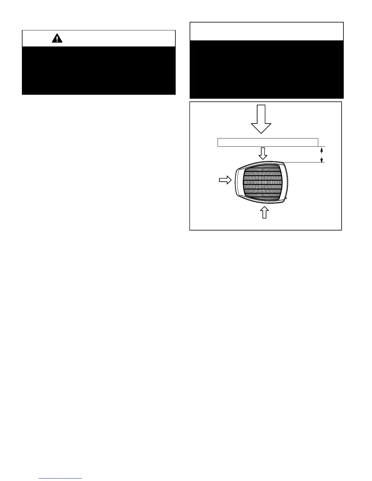
Guidelines for unit positioning, clearances, and stabilization on various surfaces.

Electrical and Wiring Procedures

Covers electrical connections, grounding, wire routing, and control wiring diagrams.

Refrigerant Line Set and Connections

Information on line set requirements, installation, brazing, and safety precautions.

System Charge

Unit Start-Up

Steps to follow for initial unit start-up, including safety checks and power.

System Refrigerant

Procedures for connecting gauge sets and checking refrigerant charge.

Subcooling Charging Method

Detailed steps for verifying refrigerant charge using the subcooling method.

Related product manuals