Page 27
II-PLACEMENT AND INSTALLATION
Make sure the unit is installed in accordance with the in-
stallation instructions and all applicable codes. See acces-
sories section for conditions requiring use of the optional
III-STARTUP - OPERATION
A-Preliminary and Seasonal Checks
1 - Make sure the unit is installed in accordance with
the installation instructions and applicable codes.
2 -
installed for loose connections. Tighten as required.
compressor access panel.
3 - Check to ensure that refrigerant lines are in good
condition and do not rub against the cabinet or
other refrigerant lines.
4 - Check voltage at the disconnect switch. Voltage
must be within the range listed on the nameplate.
voltage corrected before starting the unit.
nameplate for maximum rated load amps.
6 -
B-Cooling Startup
Operation
1 -
according to instructions provided with thermostat.
2 - No Economizer Installed in Unit -
compressor 1 and both condenser fans. An increased
Units Equipped With Economizer -
compressor 1 and both condenser fans. When
outdoor air is not acceptable unit will operate as
though no economizer is installed.
3 - Units contain two refrigerant circuits or stages. See
4 - Each refrigerant circuit is separately charged with
amount of charge.
to check refrigerant charge.
C-Safety or Emergency Shutdown
Three Phase Scroll Compressor Voltage Phasing
Three phase power supplied to the unit disconnect switch
must be phased sequentially to ensure the scroll com-
pressor and indoor blower rotate in the correct direction.
Compressor and blower are wired in phase at the factory.
1 - Observe suction and discharge pressures and
blower rotation on unit start-up.
2 -
must rise and blower rotation must match rotation
blower rotation is not correct:
3 - Disconnect all remote electrical power supplies.
4 -
the line side of K2 contactor or disconnect switch if
installed. Do not reverse wires at blower contactor.
Make sure the connections are tight. Discharge and
suction pressures should operate at their normal
start-up ranges.
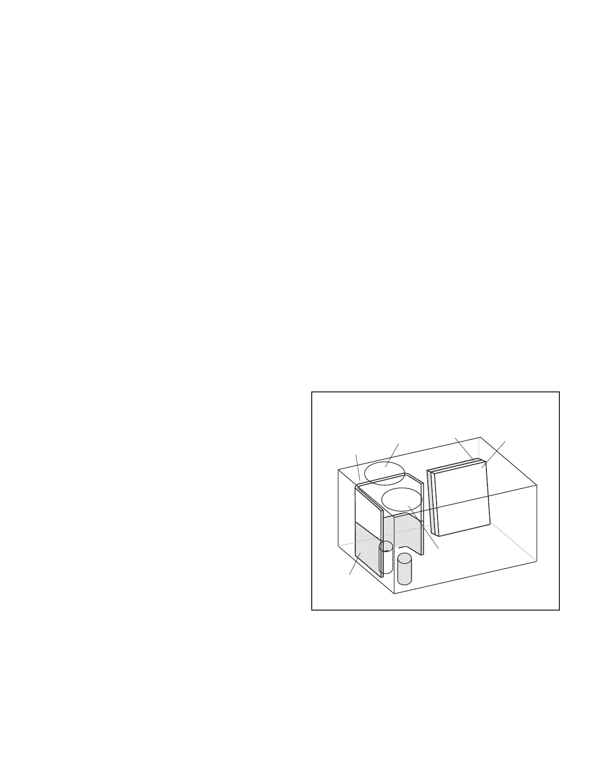
(BOTH FANS ARE ENERGIZED
WITH A Y1 DEMAND)
INDOOR
COIL
STAGE 1
2
1
INDOOR
COIL
STAGE 2
OUTDOOR
COIL
STAGE 1
OUTDOOR
COIL
STAGE 2
OUTDOOR
FAN 1 (B4)
OUTDOOR
FAN 2 (B5)
FIGURE 13
 Loading...