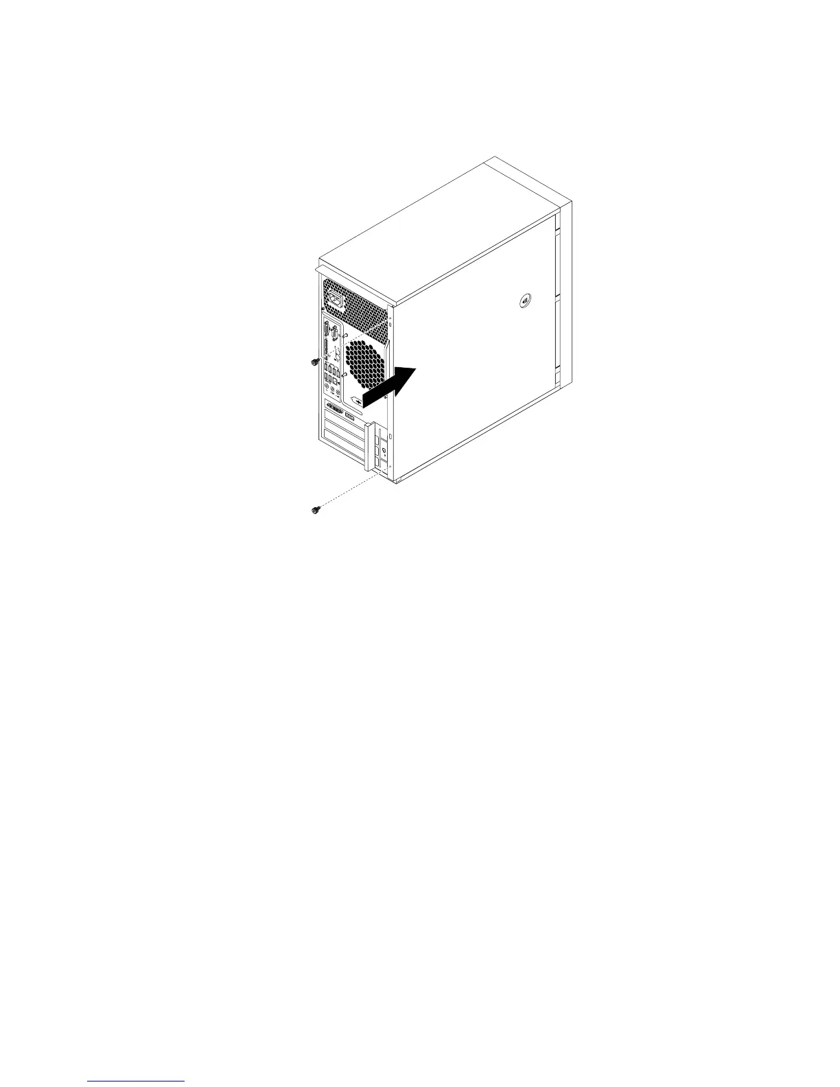
4.Positiontheservercoveronthechassissothattherailguidesonthebottomoftheservercoverengage
therailsonthechassis.Then,slidethecovertothefrontoftheserveruntilitsnapsintoposition.
Figure70.Reinstallingtheservercover
5.Installthescrewstosecuretheservercover.
6.Locktheservercoverifyouhaveaservercoverlock.See“Integratedcablelock”onpage92or
“Padlock”onpage92
.
7.Reconnecttheexternalcablesandpowercordstotheserver.See“Frontviewoftheserver”onpage
13
and“Rearviewoftheserver”onpage14.
8.Dependingonthepartsyouinstalledorreplaced,youmightneedtoconfirmtheupdatedinformationin
theSetupUtilityprogram.RefertoChapter5“Configuringtheserver”onpage23.
Note:Inmostareasoftheworld,LenovorequiresthereturnofthedefectiveCustomerReplaceableUnit
(CRU).InformationaboutthiswillcomewiththeCRUorwillcomeafewdaysaftertheCRUarrives.
Connectingthecables
Attention:Topreventdamagetoequipment,connectthepowercordsaftercompletingtheparts
replacement.
Iftheservercablesandconnectorpanelhavecolor-codedconnections,matchthecolorofthecableend
withthecoloroftheconnector.Forexample,matchabluecableendwithabluepanelconnector,ared
cableendwitharedconnector,andsoon.See“Rearviewoftheserver”onpage14
foranillustrationofthe
I/Oconnectorsontherearoftheserver.
Connectingexternaldevices
Ifyouinstallasupportedoptionaladapter,youcanattachexternaldevicestotheserver.
Toattachanexternaldevice,dothefollowing:
Chapter6.Installing,removing,orreplacinghardware91
 Loading...