Mechanical installation
Mounting
Mounting the fixed cover
5
39
Lenze • BA 12.0023 • 9.0
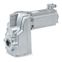
5.3.8 Mounting the fixed cover
for size 09, 11 and 14
Note!
This cover can be ordered optionally and is loosely enclosed with the
shipment!
2
x
x
3x120°
1
3
Fig. 10
1 Protection cover 3 T hread reducing sleeve
2 Cheese head screw
1. Screw the three reducing bushes (3) into the flange with a screwdriver so they are
flush and staggered by 120°.
2. Fasten the protective cap (1) over the reducing bushes (3) on the flange using
three cheese head screws (2).
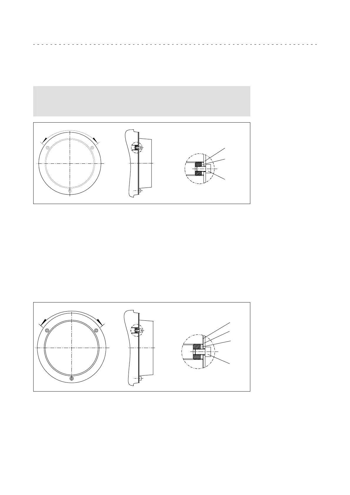
5.3.9 Mounting the hoseproof hollow shaft cover
for size 09, 11 and 14
1
3
2
4
3x120°
1 Protection cover 3 Reducing bush
2 Cheese head screw 4 Seal
1. Screw the three reducing bushes (3) into the flange with a screwdriver so they are
flush and staggered by 120°.
2. Fit seal (4) between flange and protective cap (1).
3. Fasten the protective cap (1) over the reducing bushes (3) on the flange using
three cheese head screws (2).
 Loading...