9
Electrical installaon
Operang instrucons I510-Cabinet
5 Electricalinstallaon
5.1 Generaloverviewoftheconnecons
The connecon diagram is considered exemplary for all voltage and power classes. Deviang
mains connecon diagrams can be found in the corresponding chapters.
5.2 EMC-compliantinstallaon
The drive system (inverter and drive) complies with the EMC Direcve 2014/30/EU if it is
installed according to the guidelines for CE-typical drive systems.
The structure in the control cabinet must support the EMC-compliant installaon with
shielded motor cables.
• Please use suciently conducve shield connecons.
• Connect the housing with shielding eect to the grounded mounng plate with a surface
as large as possible, e. g. of inverters and RFI lters.
• Use central earthing points.
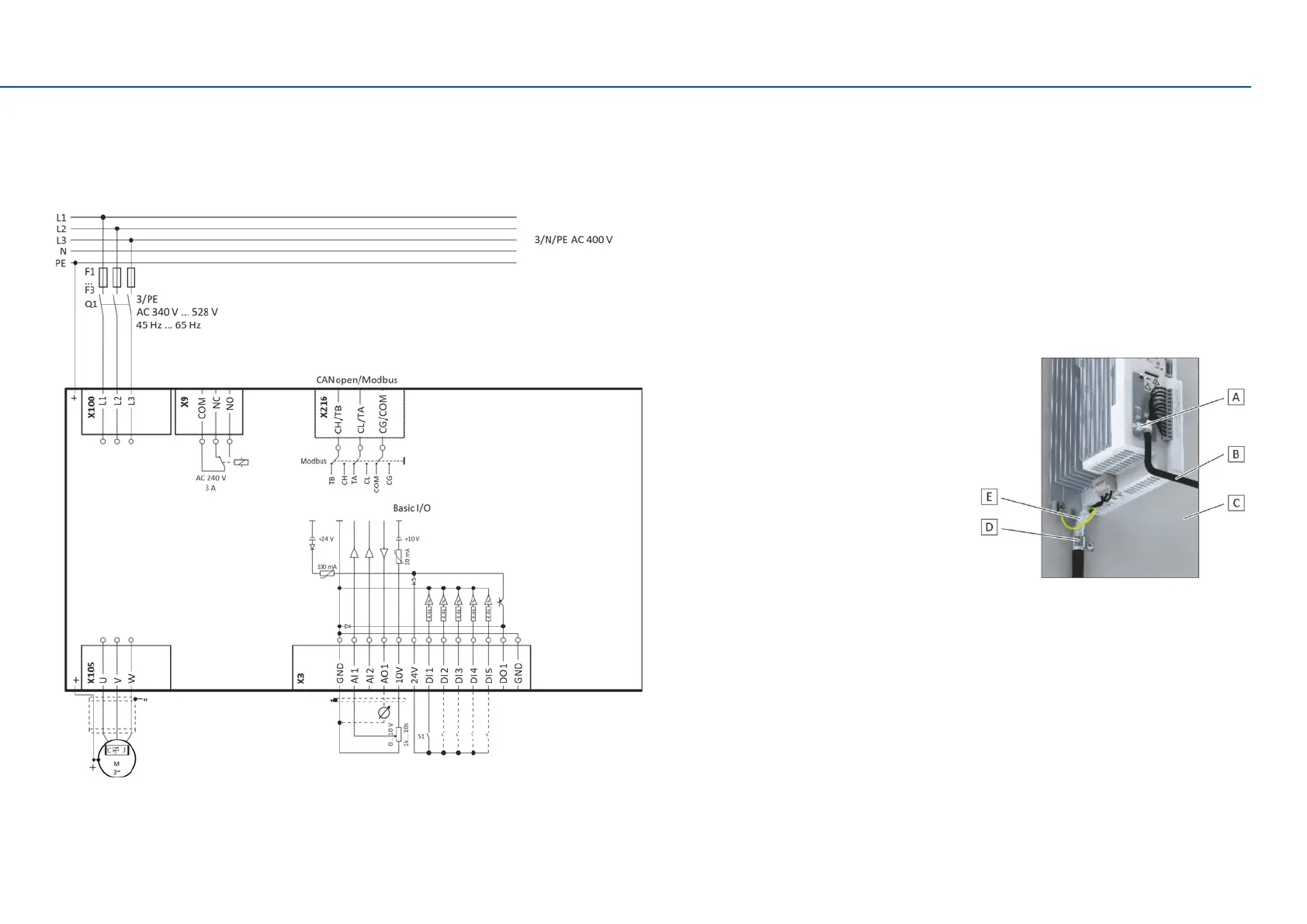
The following gure shows an example of eecve wiring with shielding on the control cabinet
wall.
A Shielding of control connecons
B Control cable
C Electrically conducve mounng plate
D Shield clamps
E Low-capacitance motor cable (C-core/core/
C-core/shield
< 75/150 pF/m ≤ 2.5 mm²; C-core/core/C-
core/shield
< 150/300 pF/m ≥ 4 mm²)
Alternavely, the motor cable can be shielded on an oponal motor shield plate.
 Loading...


