Operating instructions i550 cabinet frequency inverter | 12
© 11/2021 · EN · www.Lenze.com
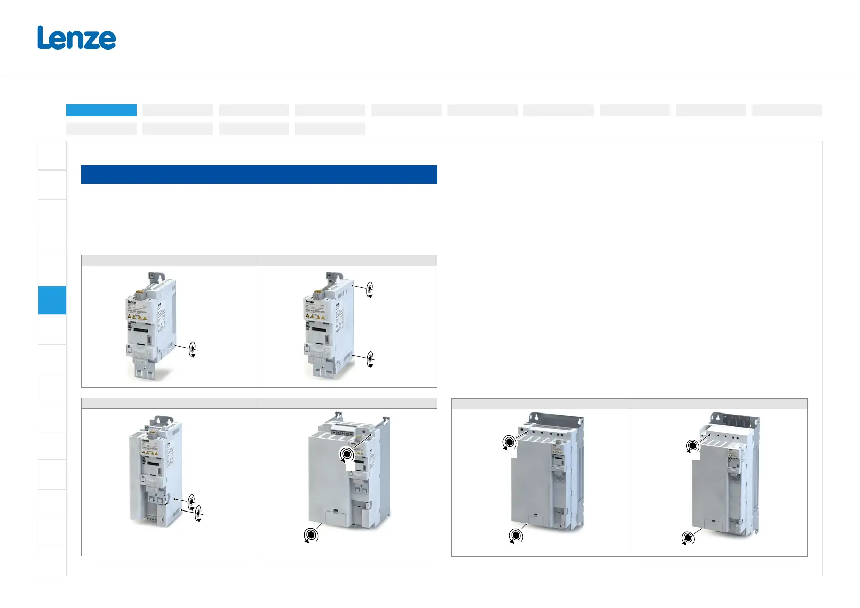
Preparation for connection to an IT system
NOTE
Internal components have ground potential
Possible consequence: The monitoring devices of the IT system will be triggered.
• Connect an isolating transformer upstream.
• Before connection to an IT system be absolutely sure to remove the screws marked on the
product with "IT".
I55AE125 ... I55AE137 I55AE155 ... I55AE222, I55BE230 ... I55BE240
TX10
TX10
TX10
I55AE230 ... I55AE311, I55BE275 ... I55BE311 I55AE315 ... I55AE322
TX10
TX10
3.0
3.0
I55AE330 ... I55AE345 I55AE355 ... I55AE411
3.0
3.0
3.0
3.0
Electrical installation
3-phase | 480 V
3-phase | 230/240V
3-phase | 400 V1-phase | 120V
1-phase | 230/240V
Control terminals
Relay output
Connection diagramPreparation
Brake resistor
Networks
Functional safety
Safe torque o (STO)
PTC input
 Loading...


