Operating instructions i550 cabinet frequency inverter | 2
© 11/2021 · EN · www.Lenze.com
General information
Identication
Information
Overview
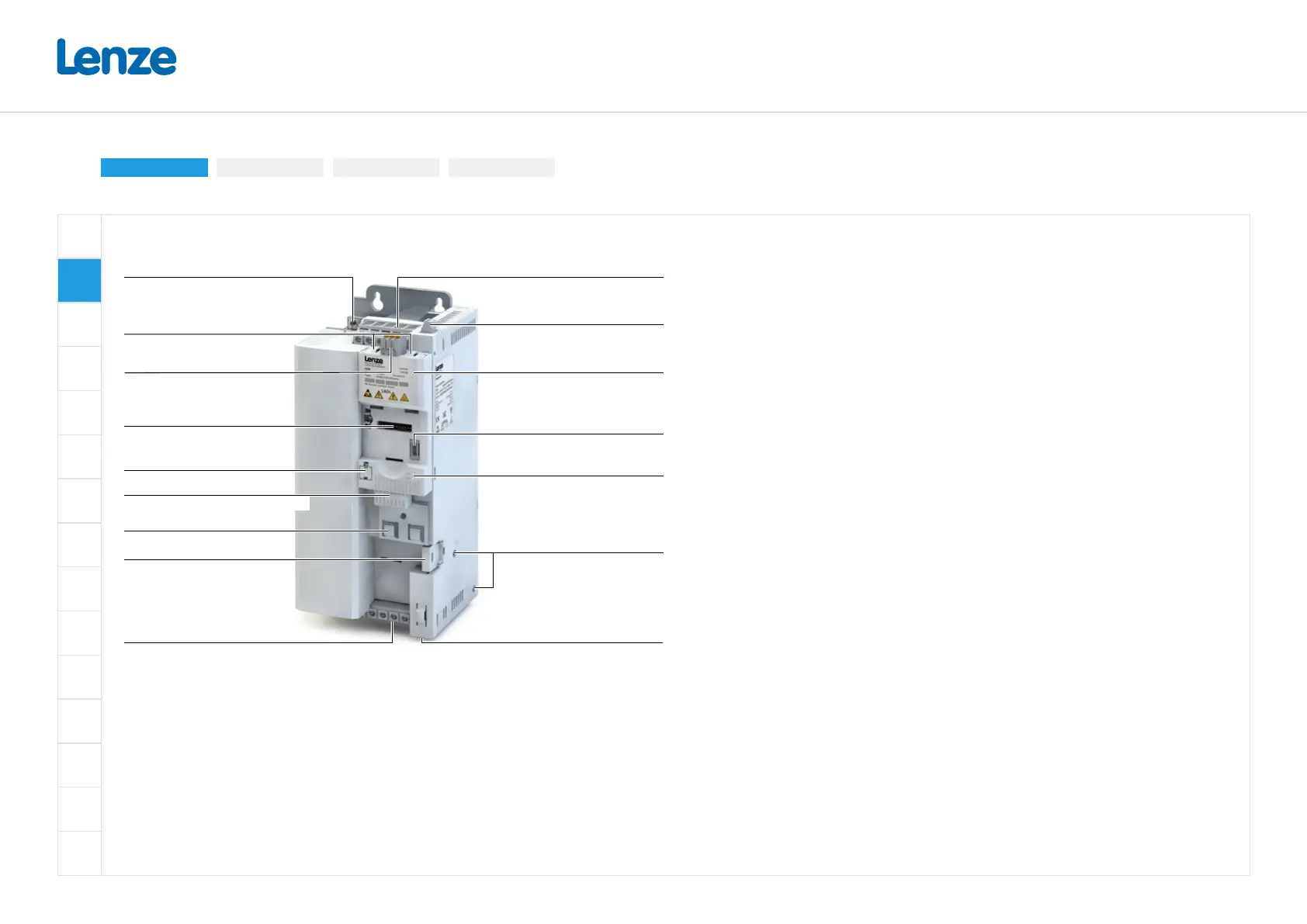
Hardware overview of the inverter
X9
X2xx
X20
X105
X3
X109
X1
X16
X100
Brake resistor connection
Slot
Diagnostic module
PTC input
DIP switch or rotary encoder switch
Motor connection
Network status LEDs
Network shield connection, Option
Inverter status LEDs
IT screw
Safety module
Shielding of control connections
Control terminals
Memory module
Interface
Network, Option
Relay output
Mains connection/DC bus
PE connection
Standard I/O oder Application I/O
Conventions
 Loading...


