Operating instructions i550 cabinet frequency inverter | 21
© 11/2021 · EN · www.Lenze.com
Brake resistor connection
NOTE
Overload
Possible consequences: Irreversible damage to the brake resistor
• Protect the brake resistor of the inverter against overload with suitable parameterization.
• The thermostat of the brake resistor can be used to establish a safety shutdown to
disconnect the inverter from the mains.
Recommendation: Use intrinsically safe brake resistors to be able to dispense with a separate
switch-o device (e.g. a contactor).
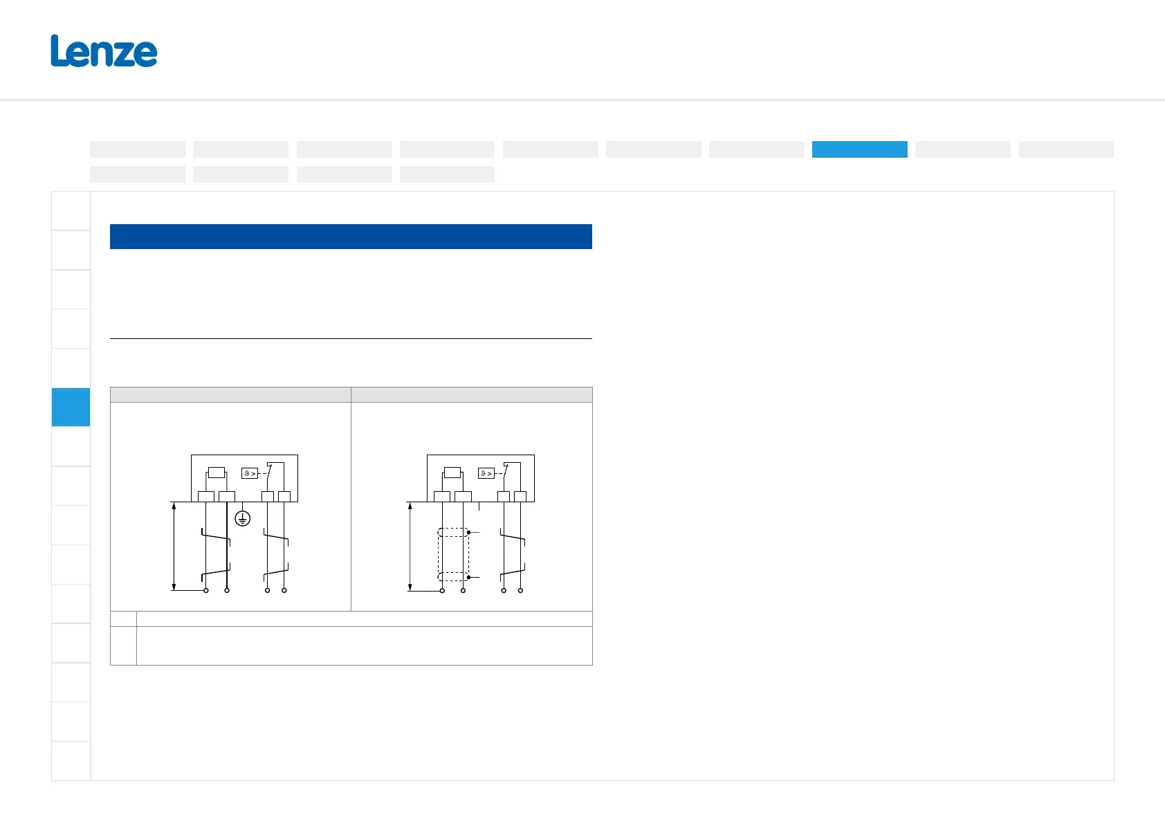
Short connection cables up to 0.5 m Long connection cables up to max. 5 m
Up to a cable length of 0.5m, the cable for the brake
resistor and that of the temperature monitoring can
be twisted. This procedure reduces problems caused
by EMC interference.
The cable of the brake resistor must be shielded
The maximum length is 5 m.
For the temperature monitoring cable, twisting is
sucient.
R
B
RB1 RB2
①
②
< 0.5 m
T1 T2
R
B
RB1 RB2
< 5 m
T1 T2
+
"
"
①
②
①
Wiring to the "brake resistor" connection on the inverter or another component with brake chopper.
②
Optional: Wiring to a control contact that is set to monitor the thermal contact. If the thermal contact
responds, the voltage supply to the inverter must be disconnected (e.g. switch o the control of the
mains contactor).
Electrical installation
3-phase | 480 V
3-phase | 230/240V
3-phase | 400 V1-phase | 120V
1-phase | 230/240V
Control terminals
Relay output
Connection diagram
Brake resistor
Networks
Functional safety
Safe torque o (STO)
PTC input
Preparation
 Loading...


