Electrical installation
Feedback connection
Resolver connection
5
36
BA33.0001 EN 2.0
5.4 Feedback connection
5.4.1 Resolver connection
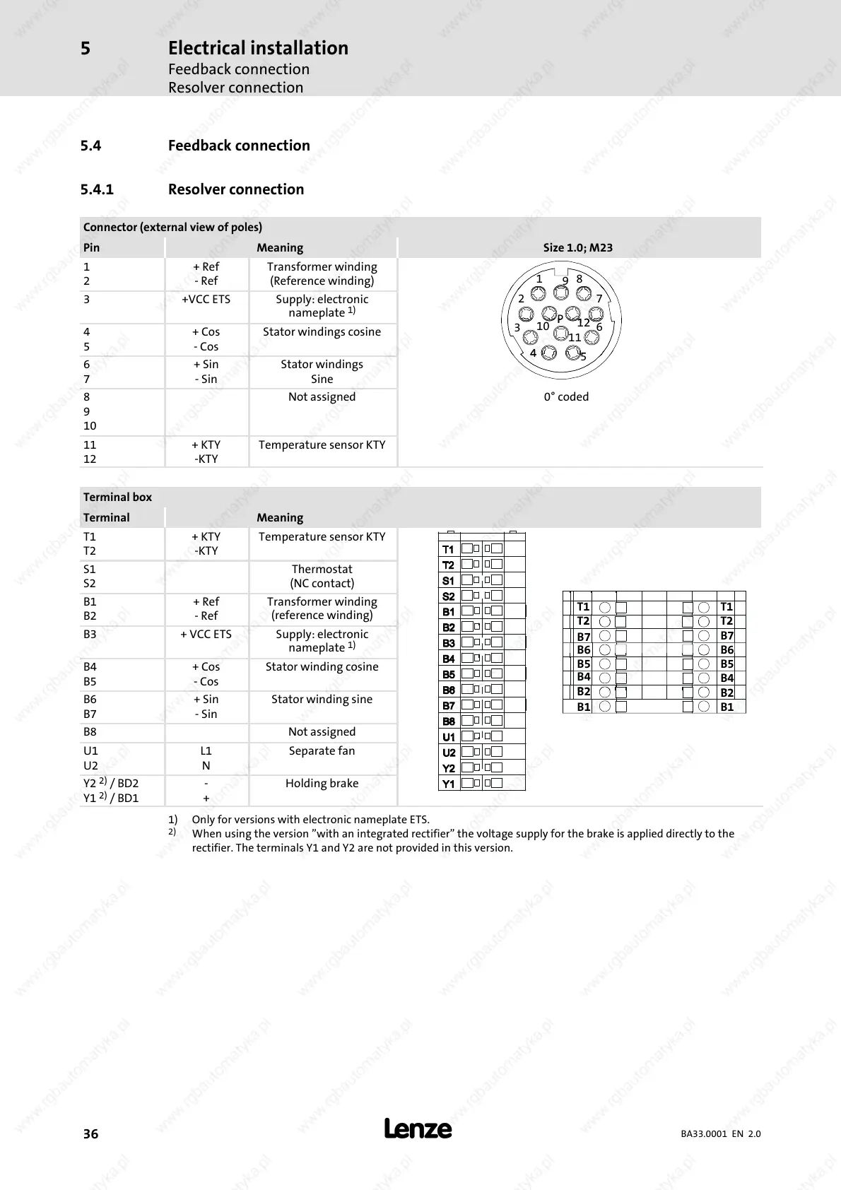
Connector (external view of poles)
Pin Meaning Size 1.0; M23
1
2
+Ref
-Ref
Transformer winding
(Reference winding)
1
9
8
3 +VCC ETS Supply: electronic
nameplate
1)
27
4
5
+Cos
-Cos
Stator windings cosine
3
6
10
11
12
6
7
+Sin
-Sin
Stator windings
Sine
5
8
9
10
Not assigned 0° coded
11
12
+KTY
-KTY
Temperature sensor KTY
Terminal box
Terminal Meaning
T1
T2
+KTY
-KTY
Temperature sensor KTY
S1
S2
Thermostat
(NC contact)
B1
B2
+Ref
-Ref
Transformer winding
(reference winding)
T2
T1
T2
T1
B3 +VCCETS Supply: electronic
nameplate
1)
B6
B7
B6
B7
B4
B5
+Cos
-Cos
Stator winding cosine
B4
B5
B4
B5
B6
B7
+Sin
-Sin
Stator winding sine
B1
B2
B1
B2
B8 Not assigned
U1
U2
L1
N
Separate fan
Y2
2)
/BD2
Y1
2)
/BD1
-
+
Holding brake
1) Only for versions with electronic nameplate ETS.
2)
When using the version ”with an integrated rectifier” the voltage supply for the brake is applied directly to the
rectifier. The terminals Y1 and Y2 are not provided in this v ersion.
 Loading...