Installation
Connections of MOBILE DCU S
Motor
5
Ò
63
EDSMDAG EN 2.0
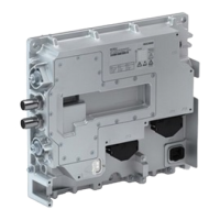
5.7.3 Motor
X3
V
max
[V AC] [mm
2
]
[AWG]
1 2
3
1 U
600
2.5
12
2 V
3 W
EMDAG049c
ƒ In addition, a equipotential bonding between motor and DC/AC inverter is required.
ƒ Install the equipotential bonding conductor in parallel to the motor cable.
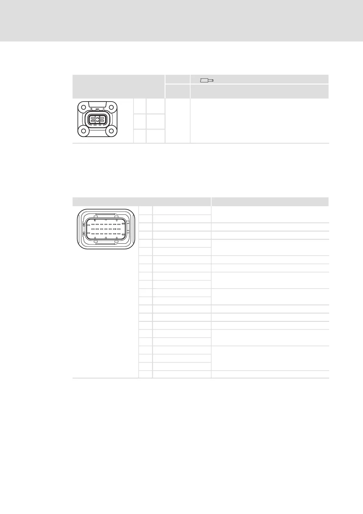
5.7.4 Control system
X1 Description
1
4
716
13 19
10
1 CAN_H
Public CAN and Private CAN network
2 CAN_L
3 CAN_L_TERM Bus terminating resistor for CAN
4 n.c. Do not use
5 TEMP_MA+
Analog thermal sensor
6 TEMP_MA−
7 TRM15 Switch on/off device
8 TRM30 Supply voltage for control electronics
9 CAN_H
Public CAN and Private CAN network
10 CAN_L
11 FLX_IN4
Digital inputs
12 FLX_IN3
13 n.c. Do not use
14 SWUP Secondary Wake up
15 TRM31 Vehicle mass, negative pole of the vehicle battery
16 FLX_IN1
Digital inputs
17 FLX_IN2
18 ID_PIN1
Address offset for setting the CAN address
19 ID_PIN2
20 ID_PIN3
EMDAG049a
21 n.c. Do not use
 Loading...