- 13 -
6. Video(uPD)-Set
6-1. Synopsis
This is a adjustment to reduce the color difference of video
signal Main/Sub Display.
6-2. Required Equipment
Service R/C, MSPG-925 Pattern Generator.
(It’s available to output the Color Bar Pattern of the NTSC,PAL)
6-3. Adjustment
(1) How to adjustment the uPD PAL
1) Select AV1 as the input with 100% 8 Color Bar Pattern
in PAL mode and select ‘AV1’ on screen.
2) After receiving signal for at least 1 second, press the
ADJ Key on the Service R/C to enter the ‘Ez - Adjust’
and select the ‘3. uPD PAL(Main&Sub)-Set’. Pressing
the Vol+ Key to adjust the uPD PAL.
3) When the adjustment is over, 'uPD64015 PAL Main
Adjustment OK’ and ‘uPD64015 PAL Sub Adjustment
OK’ is displayed. If the adjustment has errors,
'uPD64015 PAL Main Error!’ or 'uPD64015 PAL Main
Error!’ is displayed.
4) Readjust after confirming the case Pattern or adjustment
condition where the adjustment had errors.
5) After adjustment is complete, exit the adjustment mode
by pressing the ADJ KEY.
(2) How to adjustment the uPD NTSC
1) Select AV1 as the input with 100% 8 Color Bar Pattern
in NTSC mode and select ‘AV1’ on screen.
2) After receiving signal for at least 1 second, press the
ADJ Key on the Service R/C to enter the ‘Ez - Adjust’
and select the ‘4. uPD NTSC(Main&Sub)-Set’. Pressing
the Vol+ Key to adjust the uPD NTSC.
3) When the adjustment is over, 'uPD64015 NTSC Main
Adjustment OK’ and ‘uPD64015 NTSC Sub Adjustment
OK’ is displayed. If the adjustment has errors,
'uPD64015 NTSC Main Error!’ or 'uPD64015 NTSC
Main Error!’ is displayed.
4) Readjust after confirming the case Pattern or adjustment
condition where the adjustment had errors.
5) After adjustment is complete, exit the adjustment mode
by pressing the ADJ KEY.
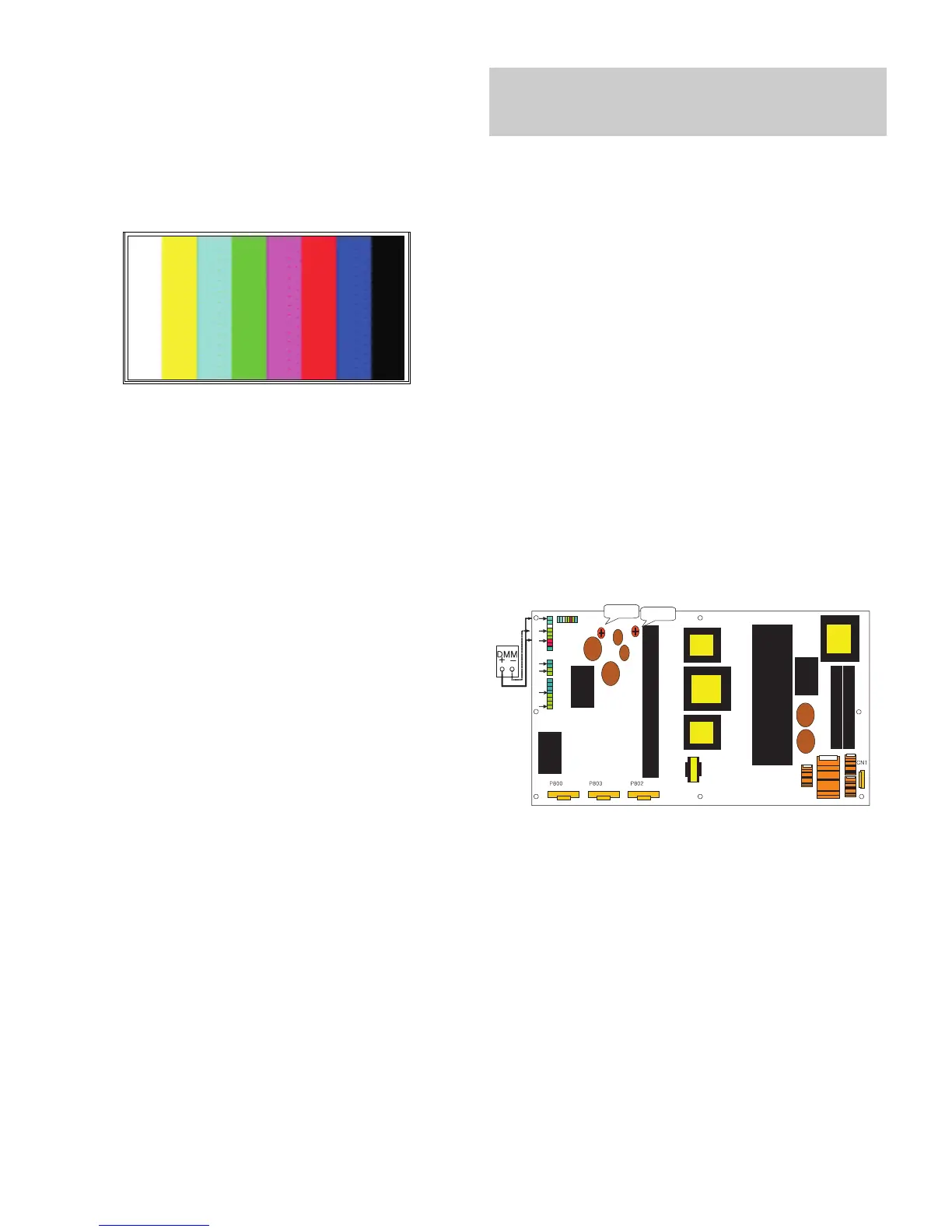
7. POWER PCB Assy Voltage
Adjustment (Va, Vs Voltage Adjustment)
7-1. Test equipment: D.M.M 1EA
7-2. Connection Diagram for Measuring
Refer to Fig.5
7-3. Adjustment Method
Adjustment Method for Power Board( P/No: 6709900019A)
(1) Va Adjustment
1) After receiving 100% Full White Pattern, HEAT RUN.
2) Connect + terminal of D.M.M to Va pin of P812, connect
- terminal to GND pin of P812.
3) After turning VR0901, voltage of D.M.M adjustment as
same as Va voltage which on label of panel right/top.
(Deviation; ±0.5V)
(2) Vs Adjustment
1) Connect + terminal of D.M.M to Vs pin of P812, connect
– terminal to GND pin of P812.
2) After turning VR951, voltage of D.M.M adjustment as
same as Va voltage which on label of panel right/top.
(Deviation; ±0.5V)
(Fig. 3) Adjust Pattern :100% 8 Color Bar Pattern
Each PCB Assy must be checked by Check JIG Set before
assembly. (Especially, be careful Power PCB Assy which can
cause Damage to the PDP Module.)
 Loading...