- 11 -
8. Tool Option Area Option Change
8-1. Profile
:
Must be changed the option value because being different with
some setting value depend on module, inch and market.
8-2. Required Test Equipment
1) Adjustment remocon.
8-3. Adjustment method
Before PCB check, have to change the Tool option and Area option.
Option values are below.
(If on changed the option, the input menu can differ the model spec.)
The input methods are same as other chassises.(Use adj Key
on the Adjust Remocon)
* After done all adjustments, Press ADJ button and compare
Tool option and Area option value with its BOM, if it is
correctly same then unplug the AC cable.
If it is not same, then correct it same with BOM and unplug AC cable.
For correct it to the model’s module from factory JIG model.
9. Color carrier Adjustment
(Inspection process)
9-1. Profile
: To have the margin about the deviation of color carrier to
satisfy the spec.
9-2. Required Test Equipment
1) Adjustment remocon.
2) Pal RF signal.
9-3. Connection
: TV set should connected with the pal RF signal(EU 5CH).
9-4. Adjustment method
(1) tuning the RF signal
ZA/ZB, TA/TB : PAL Philips Pattern (with Color Bar)
(2) push the “adj” key in the adjustment remocon.
10. POWER PCB Assy Voltage
Adjustments (Va, Vs Voltage adjustments)
10-1. Profile
: To supply the Va, Vs voltage that the module want.
10-2. Required Test Equipment
(1) Stick for adjustment.
(2) DMM.
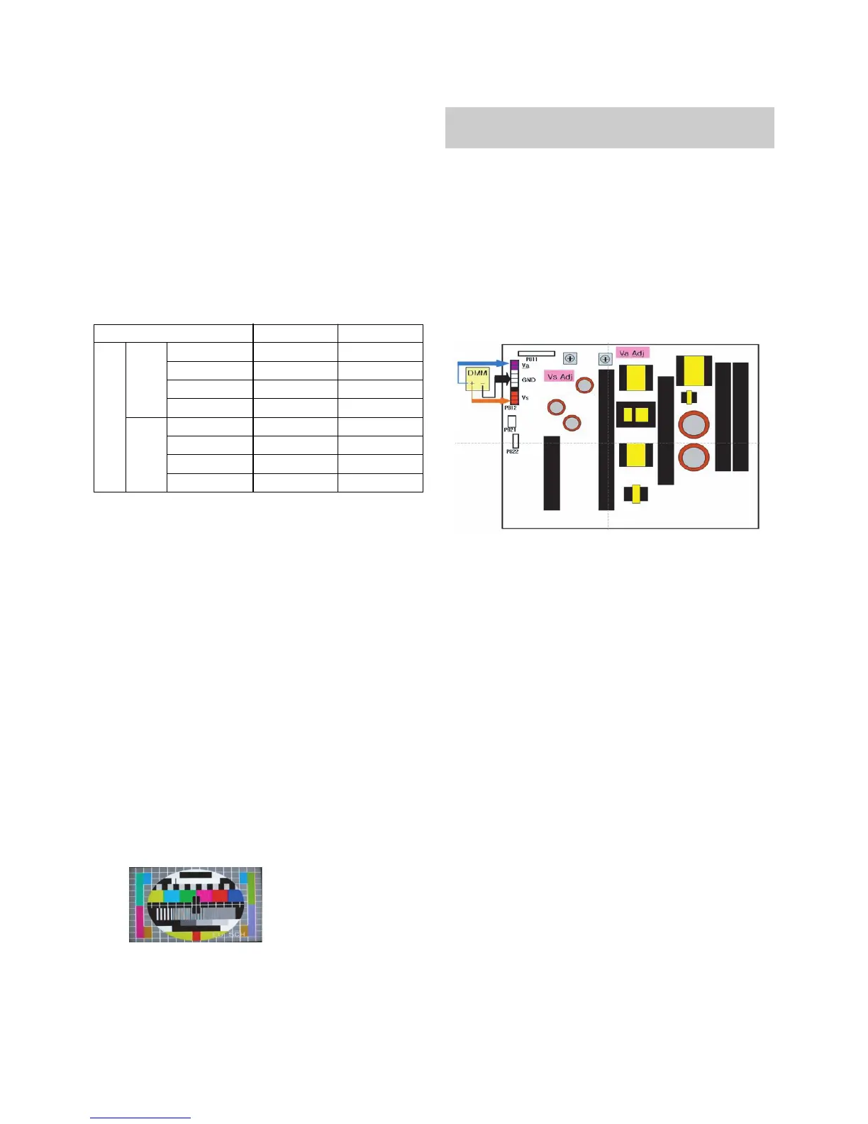
10-3. Connection structure
10-4. Connection Diagram for Measuring
: refer to (Fig. 1)
10-5. Adjustment Method
(1) Va Adjustment
1) After receiving 100% Full White Pattern, HEAT RUN.
2) Connect + terminal of D. M..M. to Va pin of P812, connect
-terminal to GND pin of P812.
3)
After turning VR901,voltage of D.M.M adjustment as
same as Va voltage which on label of panel right/top.
(deviation;
±
0.5V)
(2) Vs Adjustment
1) Connect + terminal of D. M..M. to Vs pin of P812, connect
-terminal to GND pin of P812.
2)
After turning VR951, voltage of D.M.M adjustment as
same as Vs voltage which on label of panel right/top.
(deviation ;
±0.5V)
(Fig. 1)
Connection Diagram of power adjustment for measuring.
Each PCB assembly must be checked by check JIG set.
(Because power PCB Assembly damages to PDP Module,
especially be careful)
42
VGA
XGA
PC5R(PC51)
PC6R
PC7R
PB3R
PC5R(PC51)
PC6R
PC7R
PB3R
TOOL OPTION ZA/ZB TA/TB
2244
2500
2756
3012
2252
2508
2764
3020
4292
4548
4804
5060
4300
4556
4814
5068
 Loading...