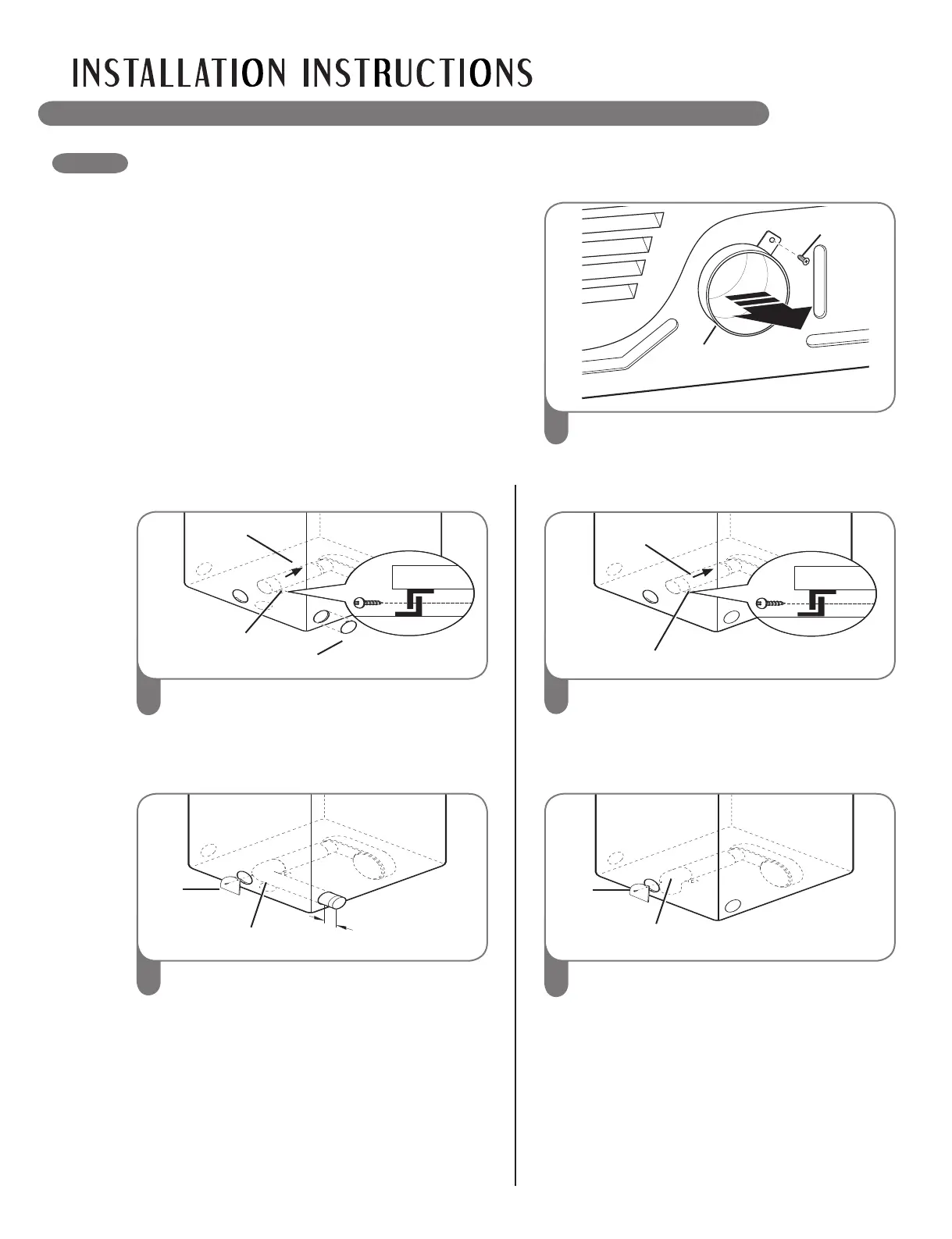
CHANGING THE DRYER VENT LOCATION
Remove the rear exhaust duct retaining
screw. Pull out the exhaust duct.
1
1
Rear
Exhaust Duct
Retaining
Screw
Press the tabs on the knockout and carefully
remove the knockout for the desired vent
opening (right-side venting is not available on
gas models). Press the adapter duct onto the
blower housing and secure to the base of the
dryer as shown.
2
Knockout
Bracket
Adapter
duct
Preassemble a 4 inches (10.2 cm) elbow to
the next 4 inches (10.2 cm) duct section, and
secure all joints with duct tape. Be sure that
the male end of the elbow faces AWAY from
the dryer.
Insert the elbow/duct assembly through the
side opening and press it onto the adapter
duct. Secure in place with duct tape.
Be sure that the male end of the duct
protrudes 1½ inches (3.8 cm) to connect the
remaining ductwork.
Attach cover plate to the back of the dryer with
included screw.
3
Elbow
Cover
Plate
OPTION 1: Side Venting
Press the adapter duct onto the blower
housing and secure to the base of the dryer
as shown.
2
Bracket
Adapter
Duct
Insert the 4 inches (10.2 cm) elbow through
the rear opening and press it onto the
adapter duct. Be sure that the male end of
the elbow faces down through hole in the
bottom of the dryer. Secure in place with
duct tape.
Attach the cover plate to the back of the
dryer with included screw.
3
Elbow
Cover
Plate
OPTION 2: Bottom Venting
wWARNING
•Useaheavymetalvent.
•Donotuseplasticorthinfoilduct.
•Cleanoldductsbeforeinstallingthisdryer.
•Toreducetheriskofpersonalinjury,adheretoall
industry recommended safety procedures including
the use of long sleeved gloves and safety glasses.
•Failuretofollowallofthesafetywarningsinthis
manual could result in property damage, personal
injury or death.
An adapter kit, part number 383EEL9001B,
may be purchased from your LG retailer. This
kit contains the necessary duct components
to change the dryer vent location.
1½”
(3.8 cm)
14
 Loading...