31
2. Status Mode Of The Connection
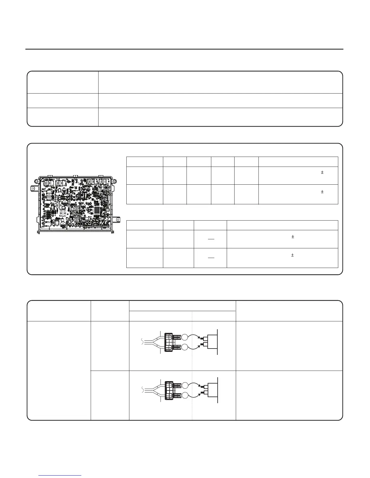
1.Power Connection
When measuring power, be sure to wear insulated gloves, to and avoid an
electric shock.
Check the Tab Relays Connection properly.
With Dryer Power On; Connector linked to Controller.
Yellow Wire
Blue Wire
Black Wire
Black Wire
Connector Housing
Connector Housing
Tap relay X4
Tap relay X5
High
Heat coil
X4
X4
X5
X5
X4 X5
Remark
Remark
Mid High
Medium
High
Mid High
Medium
Temperature Control below 68 4°C.
Turn on Heater1 and Heater2.
Temperature Control below 70 4°C.
Turn on Burner
Temperature Control below 47 4°C.
Turn on Burner
Temperature Control below 52 4°C.
Only Turn on Heater1.
on
on
O
O
onoff off
on on on
Low
Extra Low
PCB ASSEMBLY LAYOUT
Low
Extra Low
Connector Housing
Black
Check the Matching color Between
Harness wire and Tab Relay.
(Black Housing – Black Tab Relay)
Check the Matching color Between
Harness wire and Tab Relay.
(White Housing – White Tab Relay)
White
Color
< Table1 > : Connection of the Tab Relay with Heater (Elec)
< Table 2 > : Connection of the Tab Relay with Burner (Gas)
< Table1 > : Connection of Tab Relay with the Tab Relay of the PCB ASSEMBLY (Elec)
Harness
Connection
Remark
PCB
Caution
Trouble Symptom
Measurement Condition
 Loading...