3
Mounting Options
After an installation area for the outdoor unit(s) is chosen, verify:
• The floor surface / chosen location has enough strength to support the weight of the unit(s) and base.
• There is enough space for piping and wiring (when installed through the bottom of the unit [Multi F MAX
outdoor units only).
• The area has sufficient slope for drainage around the foundation to ensure condensate thoroughly flows
away from the outdoor unit condensate drain connection(s) to a drain (if present).
• Run-off from defrost mode will not accumulate and freeze on sidewalks or driveways.
•
Avoid placing the unit(s) in a low-lying area where water may accumulate.
• If installing the outdoor unit on a roof, check the strength of the roof.
• When installing on a wall (with field-supplied brackets), roof, or rooftop, securely anchor the mounting
platform with nails and / or wiring, taking into consideration the possibility of strong winds
or earthquakes.
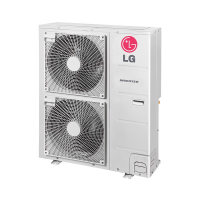
Example of Using an Insert for
a Hole in a Reinforced Concrete
Beam.
Concrete Beam
Insert
Suspension Bolt
Polyblock /
Anti-Vibration
Material
Nail Securing
Polyblock
M10
Anchor Bolt
3
13/16
Unit: Inch
Close up of a Bolt Attachment.
Outdoor Unit Platform Concrete Specifications
• Concrete foundations must be made of one part cement, two parts sand, and four parts
gravel.
• The surface of the foundation must be finished with mortar with rounded edges, and
weatherproofed.
• Ensure that the concrete platform will not degrade easily, and has enough strength to bear
the weight of the unit.
• Concrete height must be a minimum of four (4) to eight (8) inches high, depending on the
outdoor unit. See the complete Multi F / Multi F MAX Installation Manual to review height,
width, etc., platform requirements for each specific outdoor unit.
Bolting the Outdoor Unit
• All four corners of the outdoor unit must be supported properly, and securely fastened.
• Include an H-beam support. Attach the corners firmly, otherwise the support will bend.
• If not otherwise directed by a structural engineer or local codes, use a M10J bolt inserted at least three (3)
inches deep into the supports. Tightly anchor the outdoor unit with the bolt and a hexagon nut.
• If there is a possibility of vibration from the outdoor unit transmitting to the building, add an anti-vibration
material to the platform.
• Seal all wiring and piping access holes with field-supplied sealing material to prevent animals and bugs from
entering the unit.
Bolting the Outdoor Unit to the
Platform (Piping Location May
Differ Depending on Outdoor Unit
Model).
Tools
• Screw Drivers (JIS for terminal
screws, Flat, Phillips)
• Pliers
• Wire Strippers, Cutters, and
Crimpers
• Hammer
• Adjustable Wrenches
• Drill and Bits
• Hole Saw
• Utility Knife
• Drop Cloth
• Pipe Cutter / Reamer
• Acetylene Brazing Outfit
• Brazing Material —15% silver
only
• Digital Multimeter and Amp
Clamp
• R-410A Flaring Tool
• Torque Wrench Set
• Dedicated R-410A Refrigerant
Manifold Gauge
• Dedicated 5/16" Premium Hoses
• Nitrogen regulator (for 550#
test)
• 1/4" to 5/16" Hose Adapters (if
needed)
• Nitrogen Tank
• Electronic Leak Detector
• 5/16" Schrader Core Removal
Tool
• Vacuum Micron Gauge
• Good Quality Digital Charging
Scale
• Vacuum Pump and Fresh Oil
• Refrigerant Recovery Unit and
Tank
Verify the tools listed below are available for use at the installation site:
Piping
Multi F System Piping
Multi F outdoor units have two (2), three (3), or four (4) sets (one vapor and one liquid) of flare-type piping connections. Number of connections
will differ depending on outdoor unit. Field-installed piping directly links one set of outdoor unit connections to one indoor unit.
Depending on the indoor unit piping size, connection sockets (included as factory-supplied accessories with the indoor units) may need to be used.
See the complete Multi F / Multi F MAX Outdoor Unit Installation Manual for specific information.
Multi F MAX System Piping
Field piping for Multi F MAX outdoor units can be installed in one of four directions: front, rear, right, and bottom. Whatever direction is chosen,
plug the access holes with field-provided putty or insulation to fill all gaps. If the piping is installed in the bottom direction, the access hole of the
base pan must be knocked out before piping work begins.
Multi F MAX outdoor units have one set (one vapor
and one liquid) of flare-type connections. Field-in-
stalled piping links the outdoor unit connections
to a branch distribution unit. If installing two (2)
branch distribution units in parallel on one (1) Multi
F MAX outdoor unit, an LG-supplied Y-Branch kit
PMBL5620 MUST be used.
Connection sockets may need to be used when
piping the branch distribution unit to indoor unit,
depending on indoor unit pipe connections. See the
complete Multi F / Multi F MAX Outdoor Unit Instal-
lation Manual for specific information. Connection
sockets are factory-supplied as an accessory with
the indoor unit, or in the case of 36k indoor units,
supplied as an accessory with the branch distribution unit
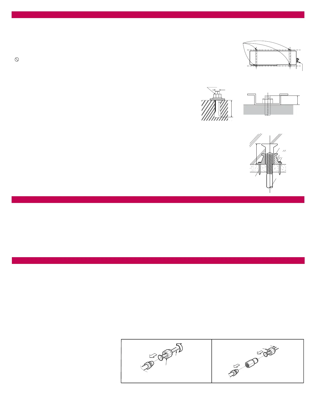
Examples of Outdoor Unit / Branch Distribution Unit to Indoor Unit Connections (With and
Without Connection Socket).
Flare nut
Piping
3/8 in. to 3/8 in.
Connection
3/8 in. to 1/2 in.
Connection
Flare side to
branch distribution unit or outdoor unit
Flare side to indoor unit
Ø3/8 in.
Flare side to indoor
unit
Ø1/2 in.
Connection socket
Flare nut
Piping
Ø3/8 in.
Ø3/8 in.
Flare side
to branch
distribution unit or outdoor unit
 Loading...