9-5. INLET VALVE ASSEMBLY
Wiring
diagram
Function
Test
points
and
Result
I
I
I
, []
I
I
i IC
MICOM
i
I
I
I
I
I
I
I
I
i
I
I
I
I
I
, Inlet valve driving circuit
[
Rg Cg
Vdc
A
b
PCB ]
CONNiCTORI
I
I
I
I
I
I
I
I
I
• I
i:Rsl I
i
I
I
- -C_
I
i
I
I
I
I
--@--
Vac
1 _ 3 4 NA
1 3 4
WH
MIAN PWB 1
_BL 11 : : _ BL
VT COMMON GY YI. BL
(BK)
_-%AIN_ _AG -_ _PRE-'_ _, ..^,,_.O'1"_ ",
i _WASHJ _VALVE J _WAS HJ _LI::/'_'_ _VA LVEJ ,''
INLET VALVE
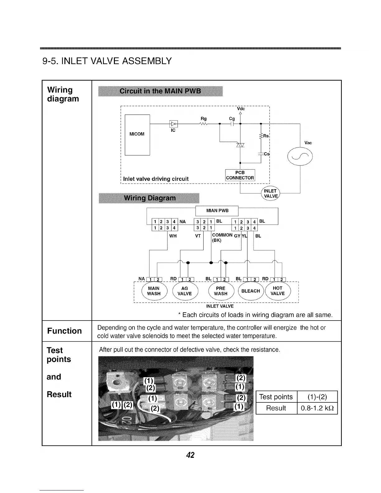
* Each circuits of loads in wiring diagram are all same.
Depending on the cycle and water temperature, the controller will energize the hot or
cold water valve solenoids to meet the selected water temperature.
the resistance.
!_ I lest points
Result
(1)-(2)
0.8-1.2 k_
42
 Loading...