1 WIRING AND CONNECTIONS
• Before commencing wiring and connection work, read the SAFETY INSTRUCTIONS AND WARNINGS and INSTALLATION INSTRUCTIONS
AND WARNINGS chaps carefully.
• A
ll wiring and connection operations must be carried out with the control unit disconnected from the electricity supply. If the disconnection
device is not in view, display a sign reading: “ATTENTION: MAINTENANCE WORK IN PROGRESS”.
1.1 Control unit connections
Terminals
Description (SEE WIRING DIAGRAM on page 2A)
AERIAL: aerial sheath input
Use a RG58- 50ohm cable.
AERIAL: aerial cable input
1
2
6
6 - 8
6 - 7
COMMAND AND PHOTOCELL COMMON: for stop, open, close, step, photo and +12V inputs.
OPEN
: NO input, commands gate opening.
16 - 15 USCITA 24 Vac: per alimentazione di vari dispositivi, 200 mA max.
19 FLASHING OR COURTESY LIGHT POWER SUPPLY COMMON
16 COMMON, INDICATOR LIGHT, 24 V ac OUTPUT
6 - 9
CLOSE: NO input, commands gate closure.
STOP: programmable NC input, commands gate stoppage.
Can be connected to safety devices such as an emergency stop bu
tton.
When the command is released automatic closure never occurs and a new movement command must be given.
Leave jumpered if no device is envisaged.
6 - 11
PHOTO1: programmable NC input for photocells or safety devices. Causes
gate stoppage during both opening and closure.
Motion resumes during opening when the photocell or safety device is disengaged.
Leave jumpered if no device is envisaged.
6 - 12
PHOTO: NC input for photocells or safety devices. Does not intervene
during gate opening; during closure causes reversal of gate
motion until open.
Leave jumpered if no device is envisaged.
19 - 17
F
LASHING LIGHT: 230 Vdc 25W max output for connecting a SPLENDOR SRL flashing light characterised by three flashing modes:
1) slow during door opening; 2) fast (flashing times halved) during closure. 3) three flashes and a pause to indicate a fault state or
travel identification.
C
OURTESY LIGHT: 230 Vdc 40W max. output for connecting a courtesy light that switches on at the start of each movement (opening
or closure and is characterised by an fix for 30 sec.)
16 - 14
INDICATOR LIGHT: 24Vac 3W max output, for connecting an indicator light that copies the function of the flashing light during movement
and that remains on when the gate is open.
19 - 18
6
- 10
STEP
: NO input, commands gate movement according to the following cycles:
SEMI-AUTOMATIC MODE: Open, stop, close, stop.
Automatic mode: open, pause, close, pause.
230Vac 50 Hz power supply
L 2
L 1
N.C. = normally closed contact – NO = normally open contact
PHASE 3
AACKNOWLEDGMENT OF THE TOTAL OPENING RADIOCOMMAND
a) P
ress , the green led (SX) will light and the red one A will
switch on.
b) H
old down the key (P1) on the radio control until all five LEDs
light .
c) Wait 25 seconds or press
two times again to quit.
ACKNOWLEDGMENT OF THE PEDESTRIANS’ OPENING
RADIOCOMMAND
a) P
ress , two times, the green (left) and the red (right)
led switch on.
b) K
eep the button (P2) pushed untile all the five leds switch on
.
The automation is now programmed.
SEMIAUTOMATIC mode is enabled: by giving the ‘STEP’ command, the automation changes movement following the sequence 1 – OPEN 2 – STOP 3 –
CLOSE 4 – STOP. Automatic re-closure is not enabled.
Once programming is complete, the
key acts as a STEP command.
P1 P2
1
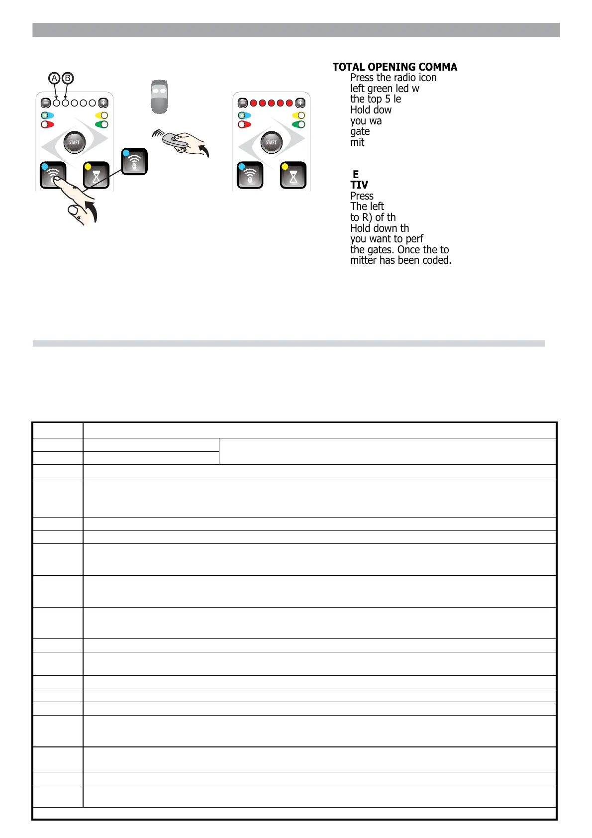
PROGRAMMING RADIO TRANSMITTERSPROGRAMMING RADIO TRANSMITTERS
TOTAL OPENING COMMANDTOTAL OPENING COMMAND
•• Press the radio icon button (top left) once thePress the radio icon button (top left) once the
left green led will light and the first (L to R) ofleft green led will light and the fi rst (L to R) of
the top 5 led’s will light.the top 5 led’s will light.
•• Hold down the button on the transmitter thatHold down the button on the transmitter that
you want to perform a total opening of theyou want to perform a total opening of the
gates. Once the top 5 led’s light the trans-gates. Once the top 5 led’s light the trans-
mitter has been coded.mitter has been coded.
•• To exit wait 25 seconds or push the radio iconTo exit wait 25 seconds or push the radio icon
button twice.button twice.
PEDESTRIAN OPENING COMMANDPEDESTRIAN OPENING COMMAND
(ACTIVE ON MOTOR 1)(ACTIVE ON MOTOR 1)
•• Press the radio icon button (top left) twice.Press the radio icon button (top left) twice.
The left green led will light and the second (LThe left green led will light and the second (L
to R) of the top 5 led’s will light.to R) of the top 5 led’s will light.
•• Hold down the button on the transmitter thatHold down the button on the transmitter that
you want to perform a pedestrian opening ofyou want to perform a pedestrian opening of
the gates. Once the top 5 led’s light the trans-the gates. Once the top 5 led’s light the trans-
mitter has been coded.mitter has been coded.
Once programming is complete the START button acts as a step commandOnce programming is complete the START button acts as a step command
 Loading...