6
fig. (7).
AC021
2
1
AC020
2
1
1
18
17
4
3
Fig.7.1
Fig.7.2
2.0 WIRING AND CONNECTIONS
• The operator must be connected to the relative Life electronic control unit (ECU).
• All wiring and connection operations must be carried out with the control unit disconnected from the electricity supply. If the disconnection
device is not in view, display a sign reading: “ATTENTION: MAINTENANCE WORK IN PROGRESS”.
The internal linear electromechanical operator wiring performed by the Manufacturer, may not be modied under any circumstances.
2.1 Electric connections
ATTENTION: the cables used must be suited to the type of installation. It is the Fitter’s responsibility to choose appropriate material.
• The power cable may be no lighter than 60245 IEC 57 ( HO5RN-F).
• Inside the power cable, one wire must be yellow and green.
• The power cable coating must be composed of a polychloroprene sheath.
• All wires must be unsheathed as little as possible (6mm at the most) and as close as possible to the connection terminals, in order to prevent accidental
contact with live parts in the event that cables disconnect from the terminals.
• Do not pre-seal cables to be fastened to the terminals using screws.
• A power cable-fastening device must be provided. Assemble the power cable so that if it comes out of its fastening device, the neutral and live
wires are taut before the earth wire.
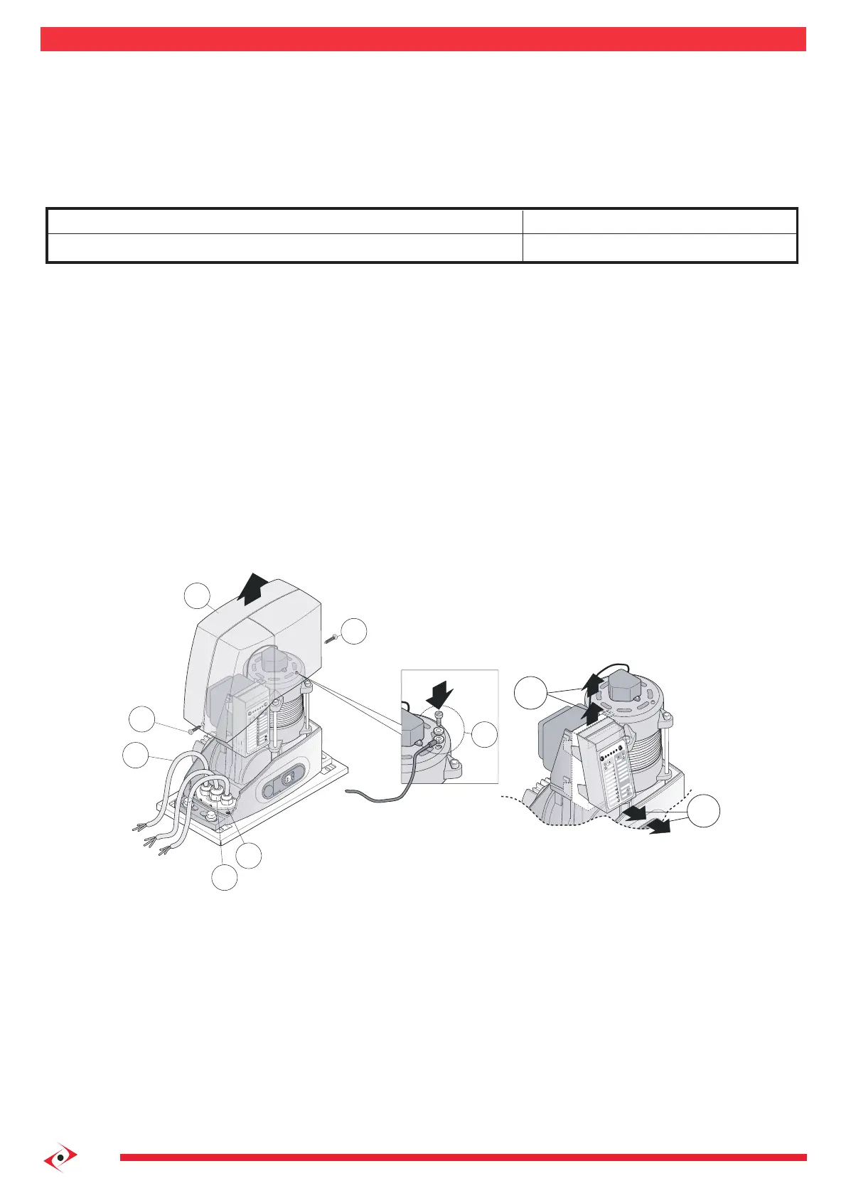
2.2 Introducing the electric wires into the operator
a) To access the ECU remove the cover (2) of the reduction gear removing the two lateral clamping screws (1).
b) Open the pre-punched holes in the cable gland door (3), insert the cable glands (17), then insert the cables (18) needed for the connections (keep
230 V and very low voltage cables separate). Leave the cables about 40cm longer
c) Assemble the cable gland door making it stick well to the edges of the seat in the operator base to prevent access to insects and dirt. See g. (7).
2.3 Electronic control unit connections
Fitters must make the connections of the 230 Vac 50 Hz electricity supply, and the various automation devices. Connections between the ECU, motor,
encoder and autotransformer have already been performed by the Manufacturer.
ATTENTION: for safety reasons, it is essential to earth the motor.
Crimp the yellow and green wire on the power cable to the loop on the upper sleeve, at the point marked by the earth symbol as indicated in g. (7.1).
To facilitate ECU connection operations and programming, it can be removed from its housing. The operation is straightforward and does not require the
use of any tools:
a) remove the ECU by pulling upwards and, compatibly with the length of the cables, rest on the edge of the operator base or hold.
Once the wiring and/or programming work is complete, place the control unit back in its recess by pressing lightly until the 4 clips snap in. See g. (7.2).
Connection
Electricity supply line
Type of cable
3x1,5 mm2 cable
 Loading...