AC013
10
7
4
Fig.5.1
Fig.5.2
Fig.5.3
Fig. (6)
B
A
AC6R M DL
AC4-6-8-12R DL
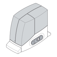
a) Remove the lid (2) of the operator by loosening the screws (1); rest the operator on the anchorage plate and manually turn the 4 M10 screws (7) with
the relative washers through 3/4 of a revolution. See g. (5.1).
b) Vertically adjust the operator using the 4 dowels (8) levelling it with the spanner (9); adjust the operator so that it is parallel to the gate. See g. (5.2).
c) Denitively fasten the operator by blocking the 4 M10 screws (7) and the relative washers with a xed or tube wrench (10). Assemble the covers
on the clamping feet (4). See g.(5.3).
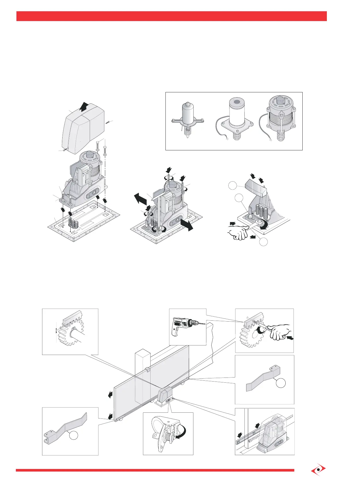
1.4 Installing operator components: rack assembly
Assemble the “gate open” (A) and “gate closed” (B) limit switch brackets at the ends of the rack, fastening them with the screws provided in the pack
as indicated in g. (6). Remember that the gate will travel 2-3 cm more, after the intervention of the limit switch, consequently adjust the position of
the brackets so that the gate does not collide with the mechanical stop plates.
1.3 Installing operator components: positioning and installation of the operator
 Loading...