8
J-BOX FOR
AUDIO INPUT
WALL PLATE
WALL STUD
ROUTE LEFT AND RIGHT
RCA CABLES INTO J-BOX
LABEL THE CABLES
"AUX INPUT"
Figure 12. Audio Input Wall Plate Rough-in
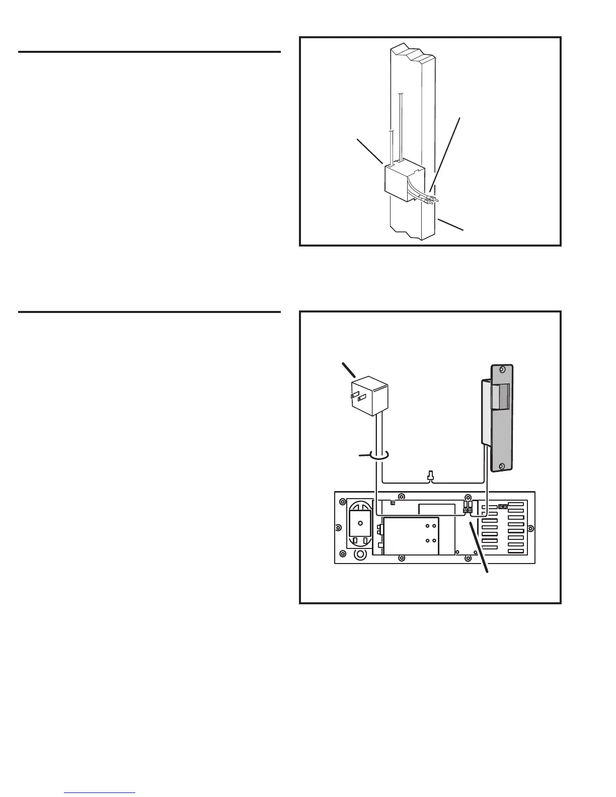
MODEL RT11
PLUG-IN
TRANSFORMER
2-CONDUCTOR
18 AWG
CABLE
MODEL DRW
ELECTRIC
DOOR STRIKE
REAR OF DMC1 MASTER
DOOR RELEASE
TERMINALS
Figure 13. Door Release Wiring
EXTERNAL MUSIC SOURCE
The DMC1 Master Station can play audio from an external
source. A commonly available audio input wall plate with a
pair of stereo RCA jacks can be wired to the DMC1 Master
Station and connected to a stereo receiver, television, DVD,
or portable music player.
✔ NOTE: The cable connection from the external audio source to the
DMC1 must not exceed 50 feet.
1. At the location for the audio input wall plate, install a single-gang
J-box at the center height of normal wall outlets. Be sure the J-box
extends past the wall stud, into the room, so it will be fl ush with the
drywall when it is applied.
2. Route two shielded RCA-to-RCA cables from the J-box to the DMC1
Master Station’s wall housing through the top left wiring access hole
or slot (see Figure 12). Leave about 12” of extra cable extending at the
wall housing end and about 6” of extra cable extending at the J-box
end. LABEL THE CABLES “Aux Input”.
3. Tie a knot in the cables inside the J-box to prevent the cables from
slipping out.
DOOR RELEASE RELAY
The DMC1 Master Station contains a dry contact relay that
can be used to control external devices. Typical applications
include activating a door strike, triggering a panic alarm
system, or controlling a home automation or lighting system.
The door release relay has normally open contacts that
are rated at 2 Amps @ 24 Volts AC/DC. The relay can be
activated from the DMC1 Master Station or remote scan
Room Stations (Model DMC1RS) by pressing the volume
up and volume down buttons together for four seconds. The
relay will deactivate when the buttons are released.
Refer to the following steps for connecting a Model DRW
Door Release Mechanism. For controlling other devices,
refer to the hook-up instructions supplied with the device.
1. Route 2-conductor 18 AWG cable from the DMC1 Master Station’s
wall housing to the door release location.
2. Route 2-conductor 18 AWG cable from the DMC1 Master Station’s
wall housing to a location for a Model RT11 Remote Transformer. The
transformer plugs into a standard 120 VAC outlet.
3. Route the two cables into the Master Station’s wall housing through
the top left wiring access hole or slot. Leave about 12” of extra cable
extending at the wall housing.
4. Zip-tie the two cables together and LABEL THE CABLES “Door
Release”.
 Loading...