4
lci1.com 574-537-8900 Rev: 05.30.19
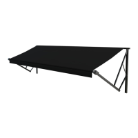
Solera
®
Slider
Installation and Owner’s Manual
(For Aftermarket Applications)
CCD-0001264
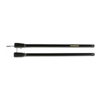
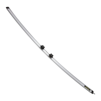
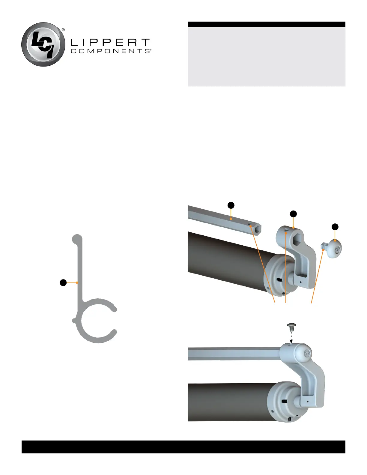
Assemble the Extension Rod and Cap
1. Slide the extension rod (Fig.2A) into the spring head
assembly torsion arm (Fig.2B), aligning the fastener
locations (Fig.2).
2. Slide the spring head assembly torsion arm end cap
(Fig.2C) into the extension rod (Fig.2A), aligning all three
fastener locations (Fig.2). Fasten using the provided
1/4” - 20 x 5/8” slotted pan head, self-tapping screw (Fig.3).
NOTE: Do not secure the second extension rod to the
spring head assembly torsion arm until the Solera Slider is
ready for installation on the unit.
fastener locations
Fig.2
Fig.3
A
B
C
Fig.1
A
Installation
All screws supporting the awning assembly MUST have a
backer within the structure of the wall of the unit. Refer to
unit manufacturer for proper location.
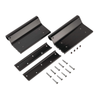
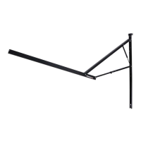
Installing the Awning Rail
Awning rail included.
1. Position the awning rail along the line where the roof and
wall meet or a minimum of 3” above the upper edge of the
slide room the Solera Slider will cover.
The awning rail must be level and parallel with the top of
slide room box of the unit.
2. After determining the awning rail’s proper location,mark
its position with a non-permanent method of marking.
3. Apply sealant to the back of the awning rail (Fig.1A).
4. Align the awning rail on the wall and secure with
#8 - 18 X 1” screws, using all fastener holes.
 Loading...