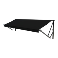
Solera
®
Awning
Smart Arm
Installation and Owner’s Manual
(For Aftermarket Applications)
www.lci1.com 574-537-8900
Page 4
Solera® Awning Smart Arm Aftermarket Manual
Installation
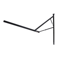
1. On the awning rail, mark the position of the centerlines
of the support arm assemblies� Make sure that the support
arm assemblies will not interfere with any lights, vents or
other obstructions�
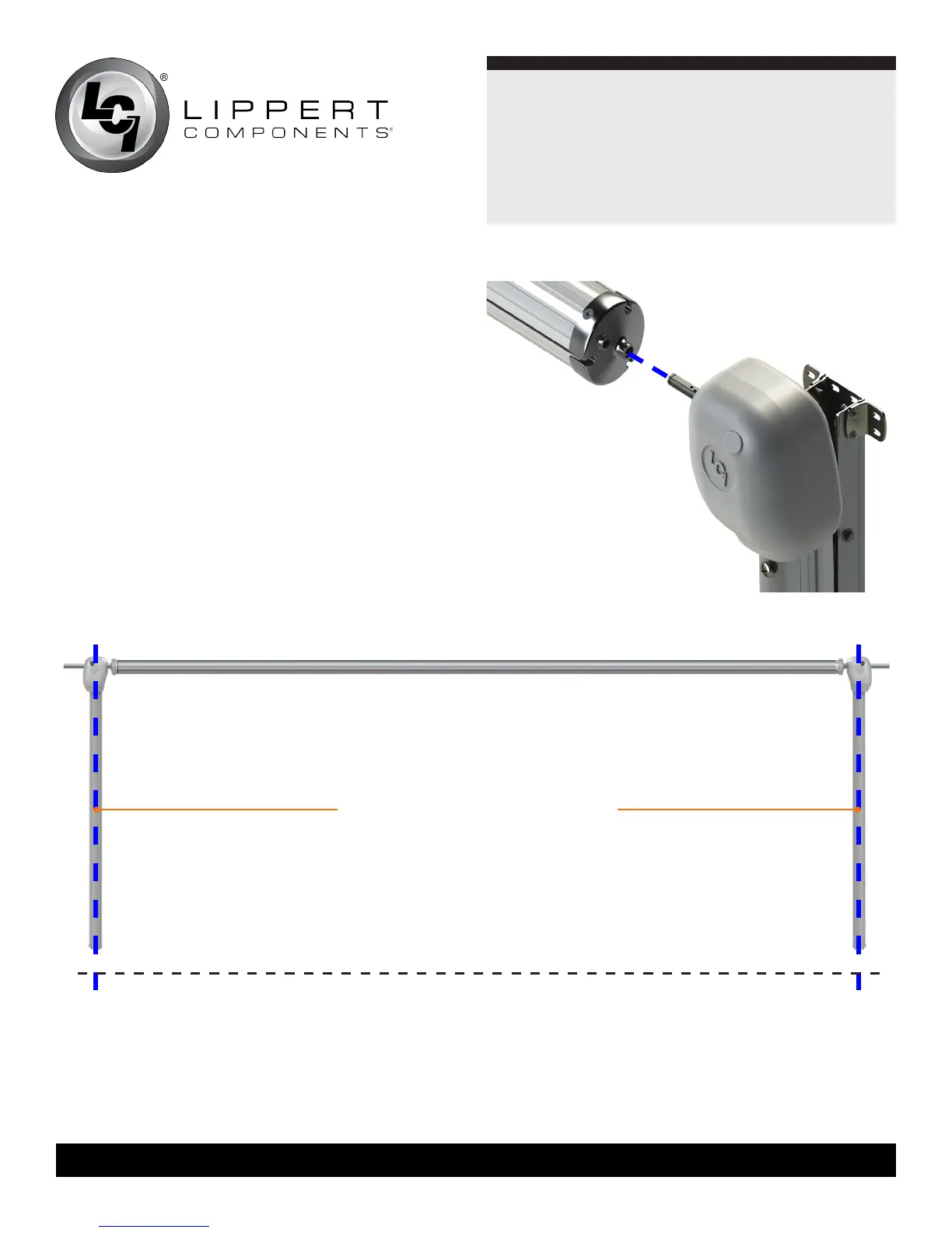
2. Using a non-permanent method of marking, mark a
perpendicular line from the awning rail down to the oor
line� This is the centerline of the support arm assembly
(Fig.2)�
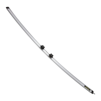
3. Insert the drive head assembly shaft into the end cap
(Fig.3)� Align the holes and secure with waxed screw�
Repeat process for idler head assembly at opposite end�
NOTE: Keep the head of the wax screw ⁄” from fastened
to avoid compromising the structural integrity of the wax
screw�
Floor Line
awning width is from centerline to
centerline of support arm assemblies
Fig.2
Fig.3
 Loading...