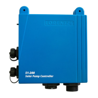
7.3 Controller Elements
Power on/off switch – The power switch is used to
start or stop the system and as a reset switch. It does not
work as power disconnect switch.
Indicator Lights – The five LED lights on the front
indicate different operational situations. For a detailed
explanation refer to chapter “10 Operating the Pump”
on page 60.
7.4 Technical Data of the Controller
Refer to “Table 2: Technical data of the PS controller” on
page 19 for an overview of the most important technical
specifications of the PS controller.
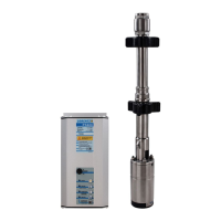
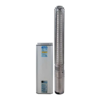
Table 2: Technical data of the PS controller
Model Pump motor:
rated power
Affiliated pump
motor
Max. DC input
voltage
Min. recommended
Vmp
Max.output
current
[kW] [V] [V] [A]
PS150
Boost
0.3 ECDRIVE 150-Boost 50 17 18
PS150 0.3 ECDRIVE 150-C 50 17 18
PS200 0.3 ECDRIVE 200-HR 100 34 11
PS600 0.7
ECDRIVE 600-HR
ECDRIVE 600-C
ECDRIVE 600-CS-F
150 68 13
PS1200 1.7
ECDRIVE 1200-HR
ECDRIVE 1200-C
200 102 9.5
PS1800 1.7
ECDRIVE 1200-HR
ECDRIVE 1200-C
ECDRIVE 1800-CS-F
200 102 14
PS4000 3.5
ECDRIVE 4000-HR
ECDRIVE 4000-C
ECDRIVE 4000-CS-F
375 238 15
 Loading...