12
Jmp2
Jmp3
Jmp1
SYSTEM
PUMP ON
OVERLOAD
WELL DRY
TANK FULL
BATTERY LOW IF FLASHES
12 34 567
low-water
sensor
probes
connect
for battery
mode
remote
float switch
NO
Com
NC
Max. 50V
Do not connect
this terminal
www.LORENTZ.de
T1
T2
T3 T4
T5
T7
V8
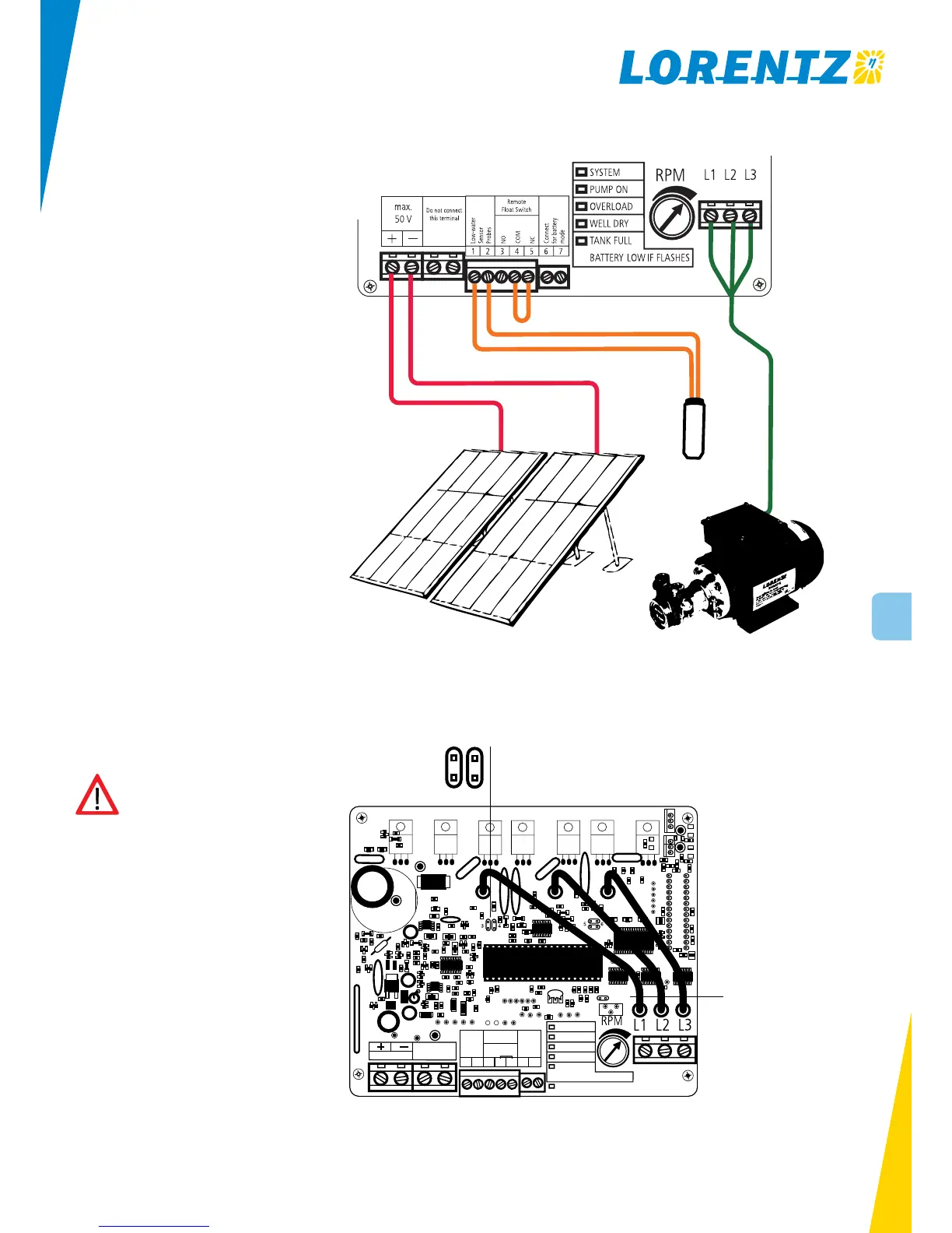
Solar direct system Voltage from panels will read
22 – 45 V when disconnected (open circuit). Use the left
power terminals to connect the solar array with the con-
troller.
The jumper wire on terminal 6 and 7 must be taken out for
solar direct mode.
Remote Tank Float Switch Connect float switch to ter-
minals 4-5 of the pump controller when it breaks contact
on rise, to turn the pump OFF. Otherwise use terminals 3-4
for opposite function.
Solar Tracking Use stranded wire for flexibility. Secure
the wires to tracker with plenty of tape. Leave a good slack
loop to allow free motion of tracker.
10.3 System Wiring for 12 – 24 V DC Systems in PV-direct Operation
10.4 Jumper Setting for PS150 Boost Mode
Before start-up check that the controller
is in PS150 Boost mode, i.e. that jumper
Jmp2 is NOT set, cf. sketch on the right.
10.5 High-run Mode
In order to set the battery high-run mode set the jump-
er Jmp1 as shown in above picture. This will increase the
Low Voltage Disconnect (LVD) settings to 12.3/24.6 V and
the re-start voltages to 13.3/26.6 V to allow pumping only
when the batteries receives charging current from the solar
array. The lifetime of the battery will be increased consider-
ably as cycling is avoided.
10.6 Power Control for PV-direct Operation
PS150 pumps require different current depending on speed
and lift. When low light conditions are present, the PV array
cannot supply the required current. If you dont use a con-
troller the voltage will drop to nearly zero, and the pump
will “stall” (like a truck trying to start in 4th gear). The
pump controller, also called linear current booster (LCB) in-
cluding Maximum Power Point Tracking (MPPT) acts like a
“gear box” in your car. This device will match the power
source to the load by transforming the voltage down while
increasing the current delivered to the motor (like an auto-
matic transmission).
1 PV module 12 V or
2 PV modules 12 V in series
Jumper Jmp1
Set to activate High-run Mode
Jumper Jmp2
Make sure the two left pints are not
connected for PS150 Boost mode
low water
sensor
 Loading...