6
5.6 Electrical Installation – Terminals
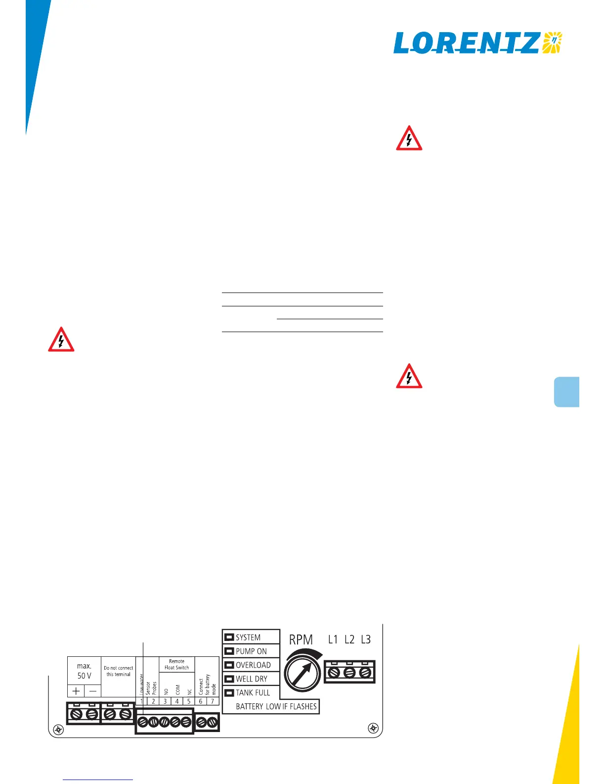
See figure 1
Power IN For PV-direct systems, a two-pole disconnect
switch may be installed between the solar array and the
controller. Switch it off to prevent shock and arc burn haz-
ard during installation and maintenance, or if the system
will be shut down for the season. For battery systems: Con-
nect the controller directly to the plus and minus terminals
of the battery. Do not connect to the load terminals of the
charger as they may be not strong enough to provide the
starting current. A 30 A slow blow fuse must be installed
between the controller and the battery.
Ground Connect the ground wire to the ground connec-
tion in the controller. Grounding helps to prevent shock
hazard if there is a fault in the motor.
L1 – L2 – L3 ECDRIVE requires four-conductor (four-wire)
cable between the controller and the motor. The three wires
L1, L2 and L3 carry power. The fourth wire carries ground.
To reverse direction of rotation reverse any two wires.
No disconnect switches must be installed
in power wires between motor pump
controller. Connecting the motor wire to
the switched-on controller might
irreparably damage it. Such damages are
excluded from the warranty.
No. 1 and 2 In order to protect the pump from being
damaged by dry running connect one well probe cable to
each terminal.
No. 3, 4 and 5 Connect any kind of external switch (NO
or NC type) for remote control of the controller. In case no
switch is used the terminals No. 4 and 5 have to be con-
nected with a short cable (factory setting). In case a NO-
switch is used (connected to the terminals No. 3 and 4) the
short cable (connecting the terminals No. 4 and 5) must re-
main installed.
No. 6 and 7 Connect these two terminals to switch the
controller to battery mode. The motor will be switched OFF
by the controller if the input voltage is below 11 V DC (for
12 V DC systems) or 22 V DC (for 24 V DC systems) respec-
tively in order to protect the battery. If the battery voltage
increases to 12 V DC (for 12 V DC systems) or 24 V DC (for
24 V DC systems) respectively, the motor will be switched
ON automatically.
5.7 Battery-based Systems
Short circuit protection Install a fuse or circuit break-
er near the power source. Use a 30 A circuit breaker or a
time-delay (slow blow) fuse installed into a rain tight dis-
connect switch. The purpose of this protection is for safety
in case of a wiring fault, and to provide a means of discon-
nect when installing or maintaining the system. PS150 con-
trollers have electronic over-current protection against mo-
tor overload.
Low-voltage disconnect function Lead-acid batter-
ies can be permanently damaged by over-discharge when
the voltage falls below a critical point. An additional charg-
er is needed for charging the batteries. To prevent this, the
PS battery system controller will turn off at low voltage,
and turn back on only after the battery has recovered sig-
nificantly.
The set points are:
System Voltage OFF ON
PS150 Boost
12 V DC 11 V DC 12 V DC
24 V DC 22 V DC 24 V DC
A controller in disconnect mode can be reset manually by
turning off/on, but it will quickly disconnect again if the
battery is not gaining a substantial recharge.
Figure 1: Terminals of PS150 controller
Terminals of the controller
5.8 Grounding and Lightning Protection
WARNING – Install proper grounding for
safety and lightning protection.
A long wire run may act like an antenna, receiving induced
surges of high voltage when lightning is present. Proper
grounding will greatly reduce risk of lightning damage to
your power system.
A proper ground system consists of a minimum of one
2.5 m/8 ft copper plated ground rod driven into the ground,
preferably in a moist spot close to the PV array.
Or, if you have a steel well casing, drill and tap a bolt hold
to make good contact to it.
In a dry, lightning prone location, use more than one
ground rod at least 3 m/10 ft apart. Bury bare copper wire
between them. Use min, 4 mm
2
/#8 ground wire (larger for
distances exceeding 6 m/20 ft).
In a rocky location, where ground rods can’t be driven,
bury (as much as feasible) 45 m/150 ft (total) of bare cop-
per wire, radiating out in two or more directions from the
PV array. Try to contact moist earth as much as possible.
WARNING – Use only the copper or
bronze electrical connectors designed
for grounding application, and BE SURE
ALL CONNECTIONS ARE TIGHT.
Connect your ground system to the METALLIC FRAME of
your PV array via min. 4 mm
2
/#8 copper wire. Also ground
metallic support structures and electrical enclosures.
5.9 Wire Sizing
Do not use undersized wire! Splice it to a larger size of wire
if your wire run is longer than 2 m/7 ft. Refer to a wire siz-
ing table. Consult a low voltage wire size chart to size the
cable size from the array to the controller or call your deal-
er or the factory for recommendations. Excessive voltage
drop will slow the pump down, but if it is unavoidable. It
will NOT cause any harm to the motor.
Wire sizing for the DC circuit Wire must be sized for
no more than 5% voltage drop at 30 A (starting).
Refer to a wire sizing chart for 12 V DC or 24 V DC,
or follow these examples:
PV-direct systems
AWG #10 wire to maximum distance of 50 ft
Metric: 4 mm
2
to max. 15 m
Battery systems
AWG #10 wire to maximum distance of 65 ft
Metric: 6 mm
2
to max. 20 m
GREATER LENGTHS For each increase by 50 %,
use next larger wire size
 Loading...