v140822
Sun. Water. Life.
BERNT LORENTZ GmbH & Co. KG Kroegerskoppel 7, 24558 Henstedt-Ulzburg, Germany, Tel. +49 (0) 4193 7548 - 0, Fax - 29, www.lorentz.de
All specifi cations and information are given with good intent, errors are possible and products may be subject to change without notice. Pictures may
differ from actual products depending on local market requirements and regulations.
7
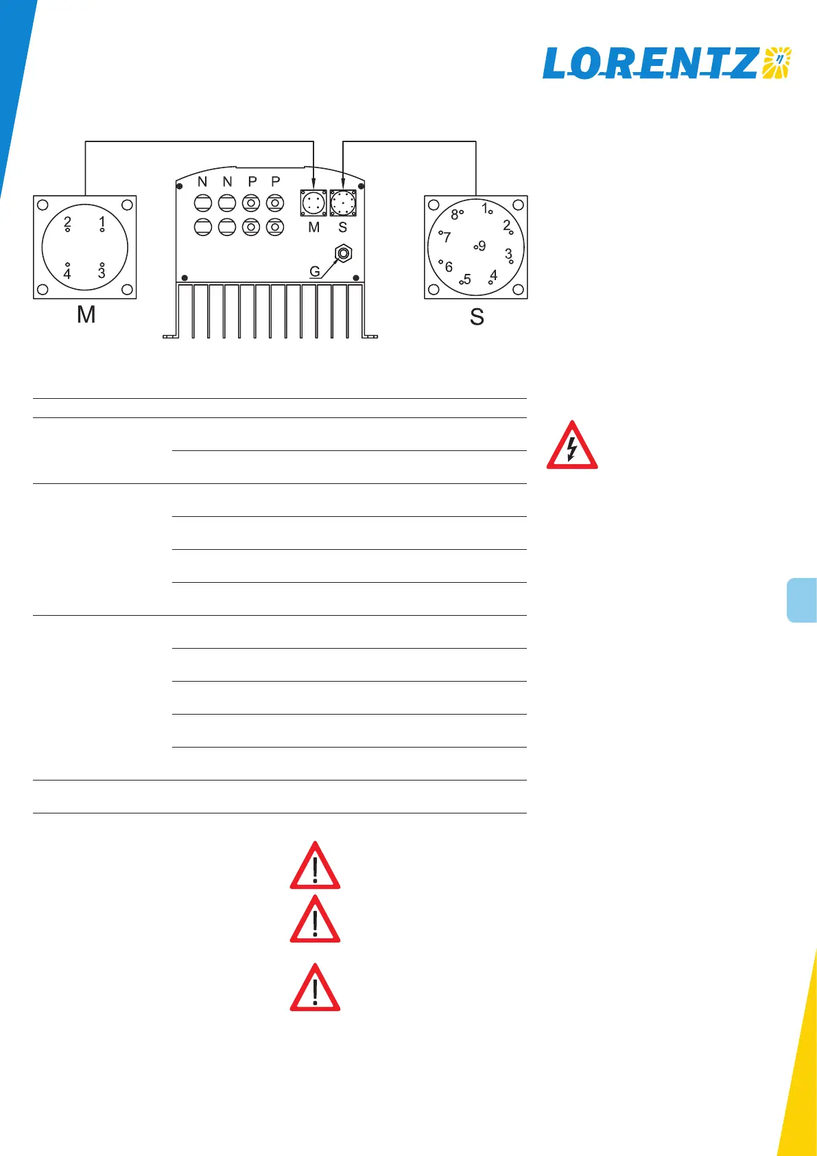
3.4 Wiring
Figure 3: Wiring diagram
Socket Terminal Connection
DC input
P connected to positive terminal of PV module
N connected to negative terminal of PV module
AC output
M-1 connected to protective ground wire
M-2 connected to U phase of the motor
M-3 connected to V phase of the motor
M-4 connected to W phase of the motor
water level sensor input
S-1 ground
S-8 float switch 1, controlled by PR 15
S-7 float switch 2, controlled by PR 16
S-6 well probe sensor 1, controlled by PR 17
S-5 well probe sensor 2, controlled by PR 18
grounding G connect to proper ground
CAUTION: Ensure the exact locations of
the DC input “P” and “N” sockets.
CAUTION: Ensure the wiring of AC
output is based on the marks of the
sockets.
CAUTION: To ensure proper operation
of the system, select the wire size
according to the following recom-
mended principle.
Prompt: Float switch 1 controlled by PR 15 and
float switch 2 controlled by PR 16 can be combined
to a dual float switch.
Prompt: Well probe sensor 1 controlled by PR 17
and well probe sensor 2 controlled by PR 18 can be
combined to a dual switch well probe.
Prompt: Please refer to chapter 4.3 Parameter for
further information on parameter settings.
3.5 DC Disconnect switch
The pump system must be equipped with proper sized DC
disconnect switch. The switch must be installed between
solar generator and controller. It must meet the following
requirements:
minimum 800V DC
continuous current rating according to maximum cur-
rent of pump controller or higher
the switch must be rated for DC current, NOT AC
A PV disconnect switch, matching all requirements above,
can be purchased from LORENTZ.
The use of a properly sized disconnect switch is an
important safety measure and obligatory for a professional
installation of a solar pumping system.
WARNING – No disconnect switches
must be installed in power wires
between motor and pump controller.
Connecting the motor wire to the
switched-on controller might
irreparably damage it. Such damages
are excluded from the warranty.

 Loading...