Step 2: Preparing the cables
(1)Label the cable ends with M+, M-, B+ and B-.
(2)Lay the battery and module cables directly next to each other. Do not yet connect the
cables.
(3)Connect the external battery fuse to the "B–" battery cable, in an easily accessible
position close to the battery.
(4)Switch off the external battery fuse: Remove the fuse insert from the fuse holder
(safety fuse) or switch off the DC line circuit breaker and secure it against being switched
on again.
(5)Connect the DC load circuit breaker to the module cables "M-" , in an easily accessible
position close to the controller.
(6)Switch off the DC load circuit breaker and secure it against being switched on again.
(7)Remove the terminal cover (release the 4 fastening screws with a screwdriver).
Step 3: Connecting the battery
Connect the battery cable and external battery fuse to the battery connection of the
controller and to the battery.
We recommend installing the external battery fuse in the "B–" cable and the
current is 1.25 to 2 times the rated current of the controller.
11
5.4 Mounting
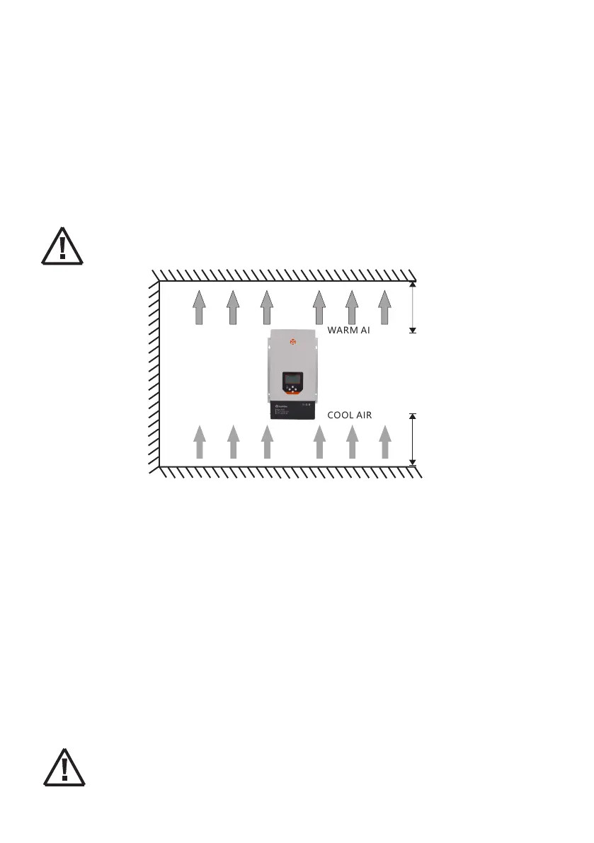
Step 1: Determination of Installation Location and Heat-dissipation Space
Do not mount the solar charge controller outdoors or in wet rooms. Do not subject the solar
charge controller to direct sunshine or other sources of heat. Protect the solar charge
controller from dirt and moisture. Mount upright on the wall on a non-flammable substrate.
Maintain a minimum clearance of 15cm below and around the device to ensure unhindered air
circulation. Mount the solar charge controller as close as possible to the batteries.
Mark the position of the solar charge controller fastening holes on the wall, drill 4 holes and
insert dowels, fasten the solar charge controller to the wall with the cable openings facing
downwards.
If the controller is to be installed in an enclosed box, it is important to ensure
reliable heat dissipation through the box.
>15CM
>15CM
COOL AIR
WARM AIR
 Loading...