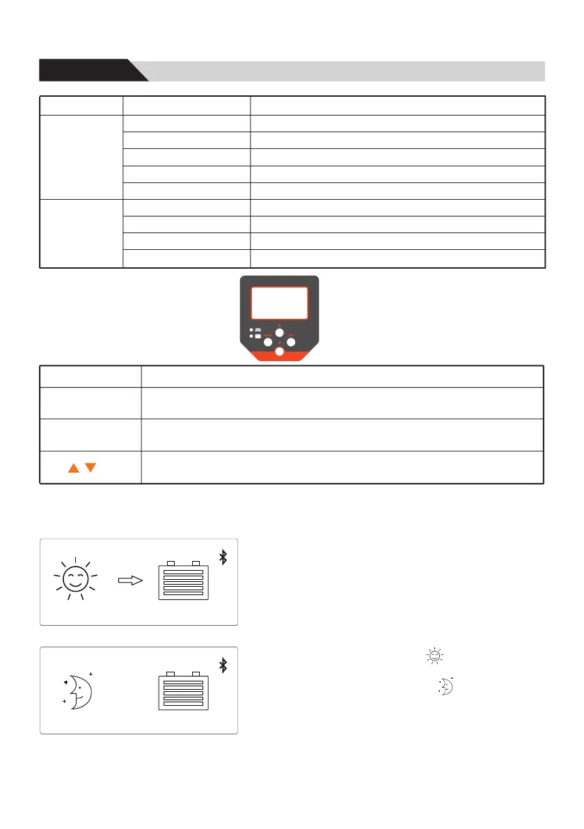
6.1 LED indicator
LED
Status
Green
(PV Panel)
Yellow
(Battery)
Key
6.2 Key function
6.3 Status display
MENU
OK
Enter or exit settings menu.
Stop blinking the selected number to confirm the change
Navigates one menu level down.
Causes the selected numeral to blink so that it can be modified.
Moves the selection bar or the display content upwards/downwards.
Increases/decreases a setting value by 1 step.
Function
2019-01-01 12:30
0W 0.0A 52.0V
485
The status display consists of data, time, communication mode, PV power/ current and
battery voltage.
The figures show the respective basic settings when
battery chargingis switched on and when the charging
is switched off.
①Date and time can be set.
②Communication mode can be set, default RS485.
If Bluetooth is connected to the mobile phone, the LCD
will display the Bluetooth icon.
③The solar module is illuminated , the controller
recognizes as daytime.
The solar module is not illuminated , the controller
recognizes as nighttime.
④The arrow symbol indicates charging of the battery.
⑤Actual charging power.
⑥Actual charging current.
⑦Battery voltage.
2019-01-01 12:30 485
2000W 21.8A 59.2V
①
②
③
③
④
⑤ ⑥ ⑦
Function
On
On
Solar panel is connected, but not charged
PV reverse connection or PV overvoltage protection
Off
Off
Fast flash(0.1/0.1s)
Fast flash(0.1/0.1s)
Slow flash(0.5/2s)
Slow flash(0.5/2s)
Flash(0.5/0.5s)
MPPT charging
Float Charging
Equal or Boost Charging
Over voltage protection
Battery is normal
Battery voltage is low
Low voltage protection
14
6, Operation
 Loading...