12 ENGLISH
Press the check button on the battery cartridge to indi-
cate the remaining battery capacity. The indicator lamps
light up for a few seconds.
Indicator lamps Remaining
capacity
Lighted O Blinking
75% to 100%
50% to 75%
25% to 50%
0% to 25%
Charge the
battery.
The battery
may have
malfunctioned.
NOTE: Depending on the conditions of use and the
ambienttemperature,theindicationmaydierslightly
from the actual capacity.
Main power switch
Tap the main power button to turn on the tool.
Toturnothetool,pressandholdthemainpower
buttonuntilthespeedindicatorgoeso.
2
1
►1. Speed indicator 2. Main power button
NOTE:Thetoolwillautomaticallyturnedoifitisleft
without any operations for a certain period of time.
Switch action
WARNING: For your safety, this tool is
equipped with lock-o lever which prevents the
tool from unintended starting. NEVER use the tool
if it runs when you simply pull the switch trigger
without pressing the lock-o lever. Return the
tool to our authorized service center for proper
repairs BEFORE further usage.
WARNING: NEVER tape down or defeat pur-
pose and function of lock-o lever.
CAUTION: Before installing the battery car-
tridge into the tool, always check to see that the
switch trigger actuates properly and returns to
the "OFF" position when released. Operating a tool
with a switch that does not actuate properly can lead
tolossofcontrolandseriouspersonalinjury.
CAUTION: Never put your nger on the main
power button and switch trigger when carrying
the tool. The tool may start unintentionally and cause
injury.
NOTICE: Do not pull the switch trigger hard with-
out pressing the lock-o lever. This can cause
switch breakage.
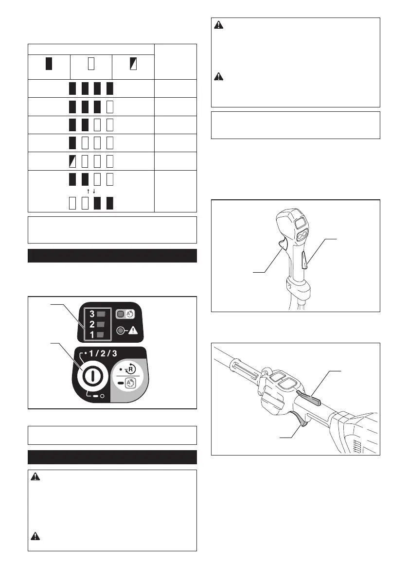
To prevent the switch trigger from being accidentally
pulled,alock-oleverisprovided.Tostartthetool,
depressthelock-oleverandpulltheswitchtrigger.
The tool speed increases by increasing pressure on the
switch trigger. Release the switch trigger to stop.
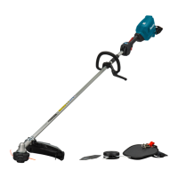
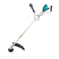
DUR369A
1
2
►1.Lock-olever2. Switch trigger
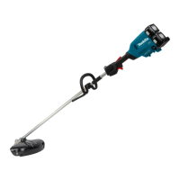
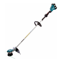
DUR369L
1
2
►1.Lock-olever2. Switch trigger
 Loading...