12 ENGLISH
FUNCTIONAL
DESCRIPTION
CAUTION: Always be sure that the tool is
checking function on the tool.
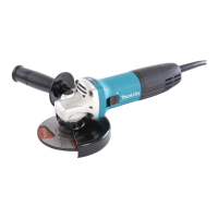
Shaft lock
WARNING: Never actuate the shaft lock when
the spindle is moving.
the tool damage.
Press the shaft lock to prevent spindle rotation when
installing or removing accessories.
Fig.1: 1. Shaft lock
Switch action
CAUTION: Before plugging in the tool, always
check to see that the slide switch actuates prop-
erly and returns to the "OFF" position when the
rear end of the slide switch is depressed.
CAUTION: Switch can be locked in the "ON"
position for ease of operator comfort during
extended use. Apply caution when locking tool in
To start the tool, press down the rear end of the slide
For continuous operation, press down the front end of
the slide switch to lock it.
Fig.2: 1. Slide switch
To stop the tool, press down the rear end of the slide
Fig.3: 1. Slide switch
Accidental re-start preventive
function
When plugging in the tool while the switch is ON, the
tool does not start.
NOTE: When the accidental re-start preventive func-
tion activates, wait more than one second, and then
start the tool again.
NOTE: When the tool is overloaded and the tool
turning on the tool again.
Soft start feature
Soft start feature reduces starting reaction.
ASSEMBLY
CAUTION: Always be sure that the tool is
any work on the tool.
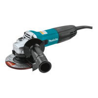
Installing side grip (handle)
CAUTION: Always be sure that the side grip is
installed securely before operation.
Fig.4
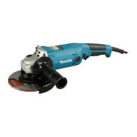
Installing or removing wheel guard
WARNING: When using a depressed center
the closed side of the guard always points toward
the operator.
WARNING:
/ diamond wheel, be sure to use only the special
For tool with locking screw type
wheel guard
Mount the wheel guard with the protrusions on the
wheel guard band aligned with the notches on the bear-
ing box. Then rotate the wheel guard to such an angle
that it can protect the operator according to work. Be
To remove wheel guard, follow the installation proce-
dure in reverse.
Fig.5: 1. Wheel guard 2. Bearing box 3. Screw
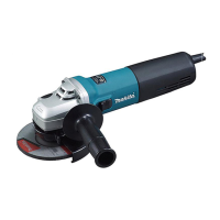
For tool with clamp lever type wheel
guard
Loosen the screw, and then pull the lever in the direc-
tion of the arrow. Mount the wheel guard with the protru-
sions on the wheel guard band aligned with the notches
on the bearing box. Then rotate the wheel guard to such
an angle that it can protect the operator according to
work.
Fig.6: 1. Wheel guard 2. Bearing box 3. Screw
4. Lever
Pull the lever in direction of the arrow. Then tighten the
wheel guard with fastening the screw. Be sure to tighten
Fig.7: 1. Screw 2. Lever
To remove wheel guard, follow the installation proce-
dure in reverse.
 Loading...