Repair
P 10 / 16
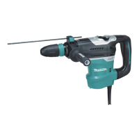
<6> Assembling chuck section
1) Assemble shoulder pin 8 to chuck ring. And then assemble leaf spring 37 to the chuck ring as illustrated in Fig. 15.
<Note> The bulge of shoulder pin 8 has to meet the hole of leaf spring 37, when assembling leaf spring
to chuck ring. See Fig. 15A.
Leaf spring 37
Shoulder pin 8
Chuck ring
Fig. 15
Fig. 15A
2) Assemble compression spring 50 and washer 40. And then, fix them on tool holder with retaining ring WR-40
and ring spring 25. See Fig. 15B.
Ring spring 25
Retaining ring WR-40
Washer 40
Compression spring 50
Tool holder
Chuck ring
Leaf spring 37
The bulge has to
meet the hole of leaf
spring 37.
Fig. 15B
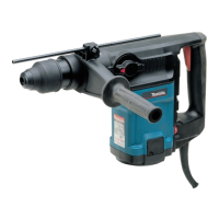
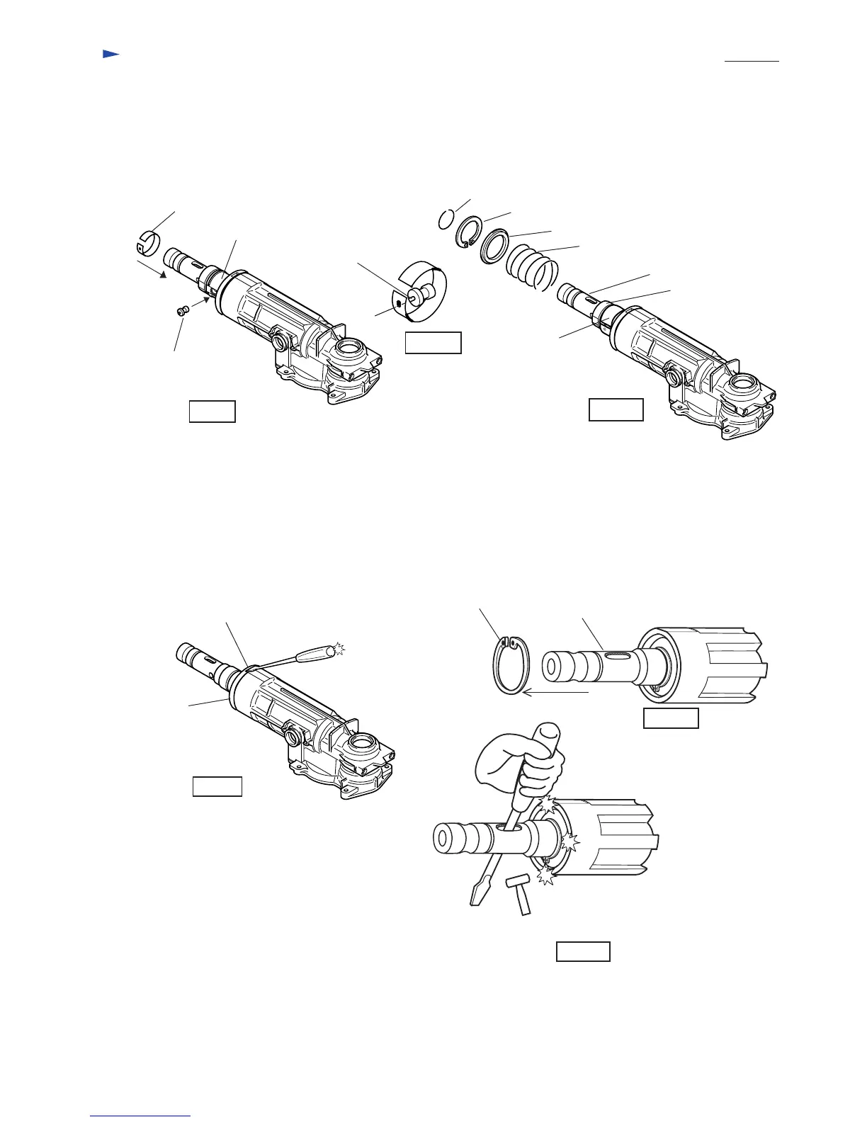
<7> Disassembling tool holder from crank housing
1) Put a driver with slotted bit into the concave portion of seal case and slightly strike the driver as illustrated in Fig. 16.
Then, seal case can be removed from crank housing.
2) Remove retaining ring R-62 with No.1R005 "retaining ring plier for hole". And pull off tool holder
as illustrated in Fig. 16A. If it is hard to remove by pulling off with your hand, you can remove tool holder
as illustrated in Fig. 16B.
Concave portion
of seal case
Seal case
Fig. 16
Slightly strike the
driver.
Retaining ring R-62
Tool holder
Fig. 16B
Fig. 16A
Slightly strike the edge of crank housing,
with holding the screwdriver with your hand.
 Loading...