9
10
11
Removing and installing valves
89
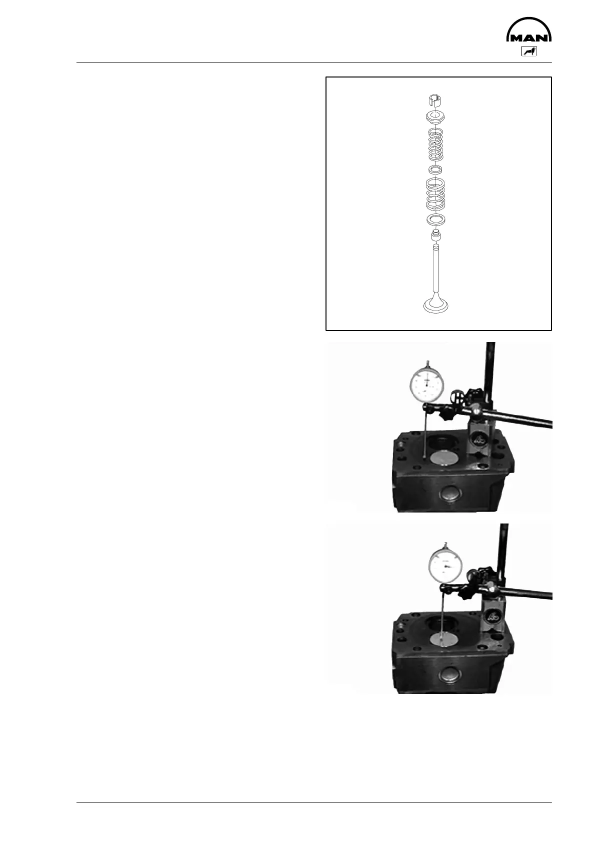
Fig. 9
Insert discs and valve springs.
The word ”TOP” facing upwards, the tight coils fac-
ing downwards. Replace damaged or weak
springs.
Fit valve discs and tapered elements.
1 Valve
2 Valve stem seal (on the inlet valve only)
3 Washer
4 Outer valve spring
5 Washer
6 Inner valve spring
7 Spring retainer
8 Tapered element
Measuring valve recess
Figs. 10 and 11
Place dial gauge holder and dial gauge on cylinder
head so that the dial gauge tip contacts the cylin-
der head and set dial gauge to - 0 -. Slew dial
gauge towards the valve disc and read off retru-
sion. If necessary, change valve and/or valve seat
insert.
1
2
3
4
5
6
7
8
2817
3531
3532
 Loading...