Technical information
20
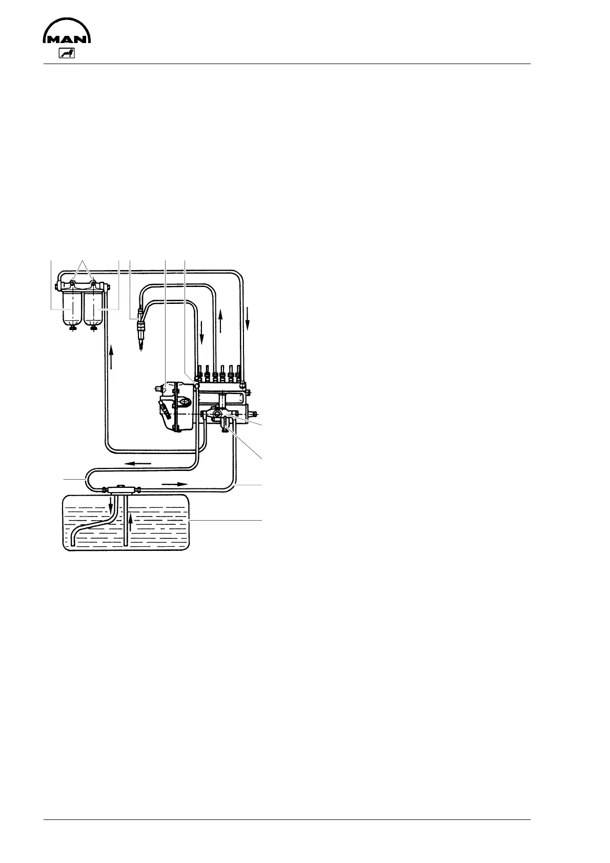
Fuel system
The fuel is delivered by the fuel lift pump via the fuel filter to the injection pump and from
there to the injectors.
The fuel is sprayed into the cylinder through four-hole nozzles fitted in screw-fit injectors
in the cylinder heads.
Excessive fuel delivered and leak fuel from the injectors flow through the return pipe back
to the tank. A strainer and a hand pump are arranged ahead of the fuel lift pump.
1 Fuel tank
2 Fuel strainer
3 Fuel lift pump
4 Parallel fuel filter
5 Bleeder screw
6 Injection pump
7 Overflow valve
8 Injection nozzles
9 Suction line
10 Return line
Injection pump
The in-line injection pump is driven via gears from the crankshaft. It is connected to the
force-feed lubricating system of the engine and consequently maintenance-free.
The centrifugal governor flange-mounted on the pump casing is a variable range gov-
ernor designed to keep the speed set by the control lever constant under conditions of
varying load.
The governor of the turbocharged engines has a full load stop controlled by the charge-
air pressure and is designed to decrease the full load fuel quantity in the low speed
range from a certain (adjustable) charge-air pressure onwards.
45 48 67
3
2
9
1
10
 Loading...