Section 2 Installation Instructions
Part Number 000002477 3/08 2-19
WATER SUPPLY AND DRAIN LINE SIZING/CONNECTIONS
Refer to “Ice Machine Dimensions” at the beginning of Section 2 for the exact locations of inlets and drains for the model you are working on.
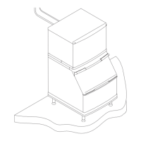
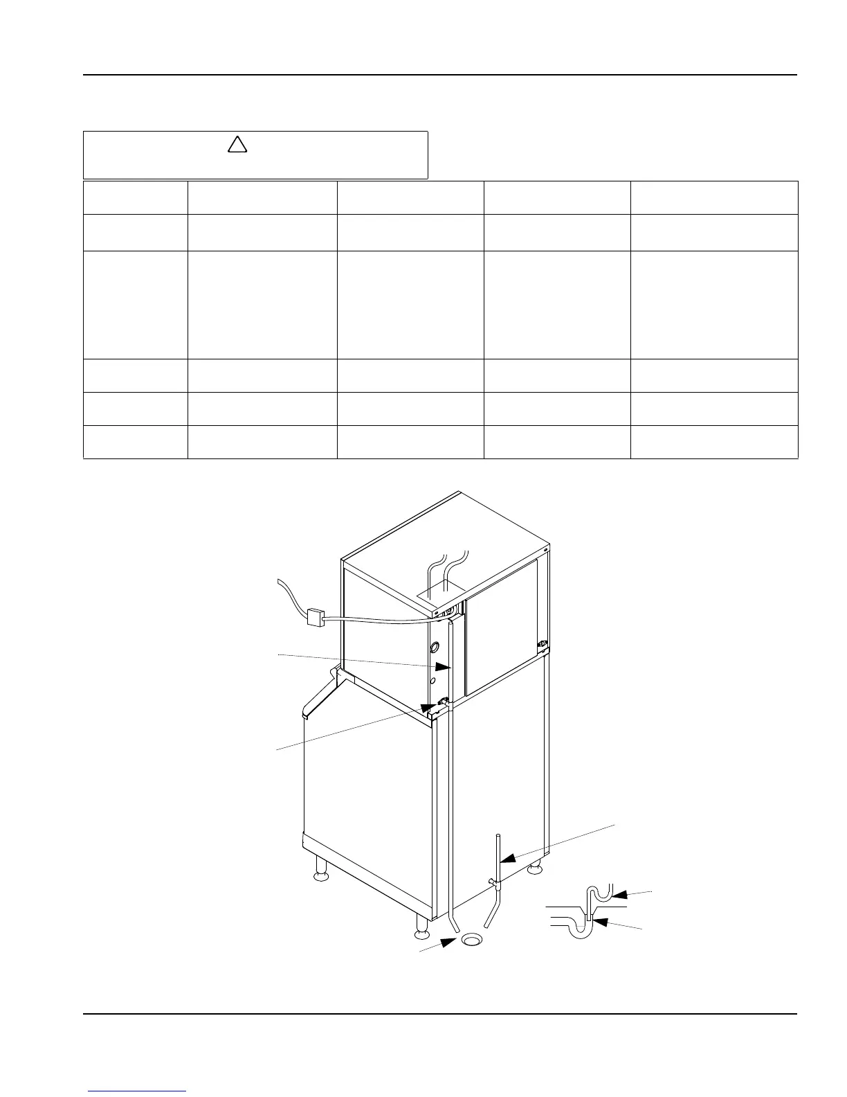
Typical Water Supply Drain Installation
Plumbing must conform to state and local codes.
Location Water Temperature Water Pressure Ice Machine Fitting
Tubing Size Up to Ice
Machine Fitting
Ice Making
Water Inlet
35
°F (1.6°C) Min.
90°F (32.2°C) Max.
20 psi (1.4 bar) Min.
80 psi (5.5 bar) Max.
3/8” Female Pipe
Thread
3/8” (9.5 mm) min. inside
diameter
Water Cooled
Condenser
35
°F (1.6°C) Min.
90°F (32.2°C) Max.
Standard
20 psi (1.4 bar) Min.
150 psi (10.3 bar) Max.
High Pressure Option
20 psi (1.4 bar) Min.
350 psi (24.1 bar) Max.
1/2” Female Pipe
Thread
1/2” (12.7 mm) min. inside
diameter
Ice Making
Water Drain
--- --- 1/2” Female Pipe
Thread
1/2” (12.7 mm) min. inside
diameter
Bin Drain
--- --- 3/4” Female Pipe
Thread
3/4” (19.1 mm) min.
inside diameter
Large Capacity
Bin Drain
--- ---
1” Female Pipe Thread
1” (25.4 mm) min.
inside diameter
18.00” VENT
(45.70 cm)
ICE MAKING WATER
DRAIN FITTING
1/2” F.P.T. (1.27 cm)
BIN DRAIN TUBING
3/4”MIN. I.D. (1.91 cm)
AIR GAP
OPEN, TRAPPED OR
VENTED DRAIN
DO NOT TRAP
MUST HAVE
AIR-GAP
INCORRECT
 Loading...