01B01-5
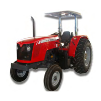
MF 400Xtra
Technical specifications
01
MF 425 MF 435 MF 440 MF 445 MF 455 MF 460 MF 470 MF 480
9. Lift hydraulics
Type ........................................................................................................... FERGUSON Category I I
Operating controls .................................................................................... Position - Depth - Transport - Response and Constant Pumping (The “Constant Pumping” is used when the combined flow is actuated, optional resource for the auxiliary
control valve, which consists of transferring the hydraulic lift pump flow to the auxiliary control valve, increasing its flow rate).
Hydraulic cylinder(s) ................................................................................. All have an inner cylinder with the option for outer auxiliary cylinders. Lift capacities marked with * below indicate use of auxiliary outer cylinders
Maximum lift capacity in kgf on the ball joints .......................................... 2100/2500* 2500/3200* 2500/3200* 3200 3200 3800 3800 3800
Hydraulic pump .........................................................................................Piston-type, ISYP model
Output (Liters/min.) / ................................................................................. 17 or 27**
* NOTE: Capacity obtained with HD type lift arms or with outer auxiliary cylinders. ** NOTE: Only when equipped with dual speed PTO or IPTO (540 and 1000 rev/min), flow rate is 27 liters/min.
Adjustment pressure for the relief valve - kgf/cm². All: 210
10. Auxiliary Hydraulic System
Number of lines and options ..................................................................... 1, 2 or 3 / double action, female terminals - quick-release coupling Options: with spring return, Kickout or valve for hydraulic motor with variable flow*.
Flow rate:
Independent type ...................................................................................... Sim Sim Sim Sim Sim Sim Sim Sim
Output = lpm............................................................................................. 42 42 42 42 42 42 42 42
Independent type with combined flow active CF (operating system)
active CF (operating system) ................................................................... 59 l/mim (for tractors with PTO of 540 rpm) and 69 l/mim (for tractors with PTO of 540 and 1000 rpm). The combined flow, when active, transfers the hydraulic lift pump flow
(17 or 27 l/min) to the auxiliary control valve, increasing flow rate. When activating the combined flow, the lift system is inoperative.
*Tractors with PTO 540 rpm: + 17 lpm **Tractors with PTO 540/1000 rpm: + 27 lpm
Maximum pressure - (Kgf/cm
2
) ................................................................. 150 150 150 150 150 150 150 150
Valve with variable flow (set in 0 to 60% of the full flow rate .................... Não Não Não Não Não Opcional Opcional Opcional
11. Steering system
Adjustment pressure for the system (relief valve) .................................... All: 145 to 150 lpm
12. Power take-off
Types...................... ....................................................... Live (PTO - Standard) Independent (IPTO - Optional)
540 / 1000 rev/min ........................................................ Optional, both for Live and Independent
Engine speed for rated speed at PTO ......................... This speed depends on the tractor and PTO configuration. The following options are available: 1700 - 1790 - 1800 - 1900 and 2000 rev/min. This information can be found in the speed decal
on the right-hand side of the operator station.
Shaft rotation direction ................................................. All: Clockwise - seen from the back.
Shaft diameter / number of splines ............................. All: PTO type 540 rev/min = 35/6 - PTO type 1000 rev/min = 35/21
Adjustment pressure for the system - IPTO:
Tractors, maintaining valve mounted by the IPTO pump inside the housing............................................... 17 bar
Tractors with maintaining valve mounted on the outside - PMV or Manifold................................................ 22 to 24 bar
 Loading...
