35
34
8.14 TROUBLESHOOTING - HEART RATE ISSUES
HEART RATE ISSUES
1) SYMPTOM:
a. No heart rate.
b. Erratic or consistently high heart rate.
2) SOLUTION:
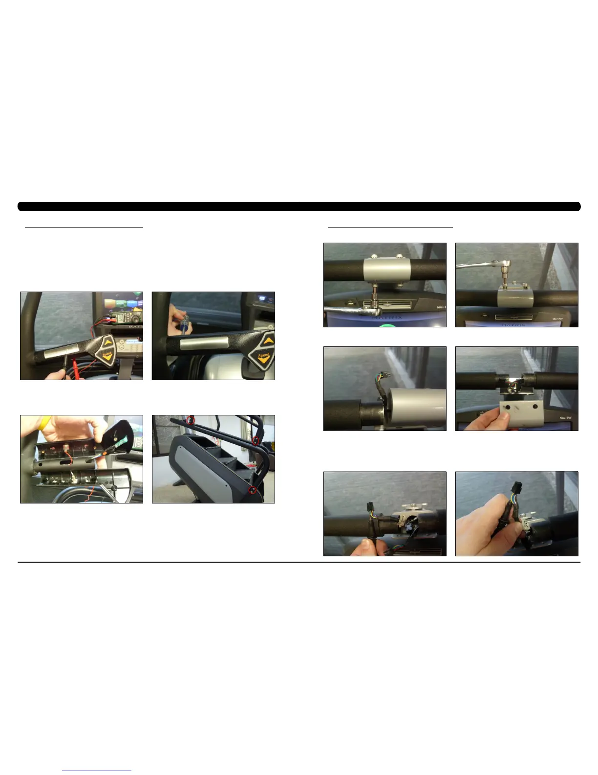
a. With a multi-meter set for DC Voltage, place one prong of the multi-meter on each of the heart rate plates on the handlebar (Figure A).
A correctly connected HR grip will have a DC Voltage reading of between .5 and 2.0VAC. Repeat this step on both HR grips. If this reading is
correct, skip to Step b. If not continue with Step a.
- Remove the screws holding the 2 halves of the HR grip together (Figure B).
- Check the connection of the heart rate grip wiring to the grips (Figure C). Replace the HR grips if any damage is seen to the plates.
- Loosen the 6 handlebar screws on each side of the unit (Figure D).
CHAPTER 8: TROUBLESHOOTING
FIGURE A
FIGURE DFIGURE C
FIGURE B
CHAPTER 8: TROUBLESHOOTING
8.14 TROUBLESHOOTING - HEART RATE ISSUES - CONTINUED
- Remove the 2 screws going into the handlebar connection frame from the bottom (Figure E).
- Remove the 3 screws going into the handlebar connection frame from the top (Figure F).
- Pull the handlebars out of the handlebar connection frame, and disconnect the HR wiring on each side (Figure G).
- Remove the handlebar connection frame from the unit (Figure H).
- Perform a continuity test on the wiring going from the HR grip to the handlebar connection frame. With a multi-meter set for ohms,
place one prong on the HR grip wiring coming out of the handlebar (Figure I) and one prong on the HR plate. The HR wiring is red, black, and
white (match red with red and white with white). For example, the red wire on the left HR grip wiring should correspond with the left top plate.
An ohm reading of less than 1 should be expected. If this reading is higher than 1, or if there is not a reading, replace this section of the HR
grip wiring.
- Repeat the previous step with the opposite side HR grip wiring (Figure J).
FIGURE FFIGURE E
FIGURE JFIGURE I
FIGURE HFIGURE G
 Loading...