63
62
CHAPTER 9: PART REPLACEMENT GUIDE CHAPTER 9: PART REPLACEMENT GUIDE
9.16 ECB REPLACEMENT - CONTINUED
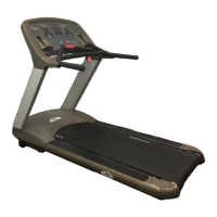
8) Loosen the remaining 2 screws to remove the 2 regular nuts (Figure E). Then remove the ECB.
9) There should be 4 screws & ferrules remaining to mount the new ECB (Figure F).
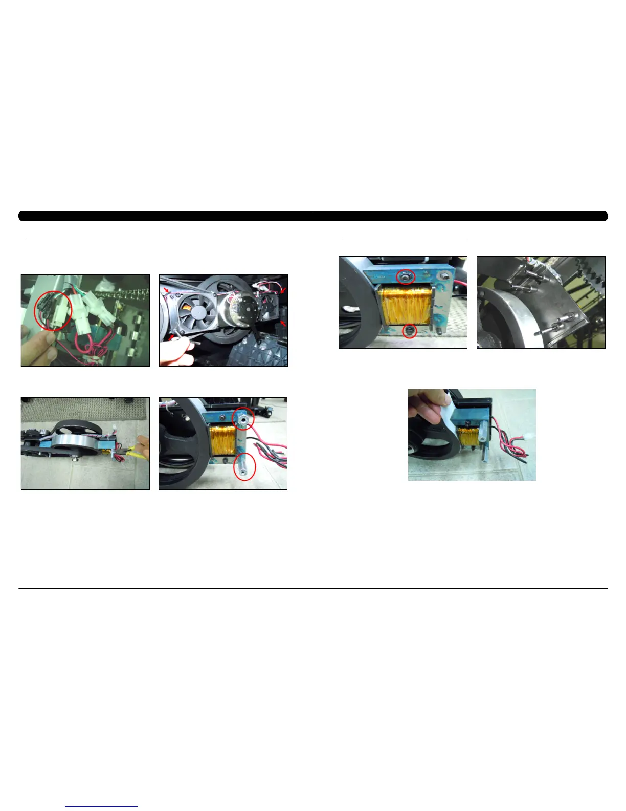
10) Install a new ECB onto the 4 screws / ferrules.
11) Before tightening the nuts, use a piece of fabric or other material that is approximately 0.5mm thick to adjust the gap between the ywheel
and the ECB (Figure G). NOTE: Once the ECB is in the correct position, torque the 4 ECB screws to 10 N-m.
12) Reverse Steps 1-9 to hook up the ECB and re-assemble the unit.
13) Test the Climb Mill for function as outlined in Section 9.21.
FIGURE E FIGURE F
FIGURE G
9.16 ECB REPLACEMENT
1) Turn off power and disconnect the cord from the machine.
2) Follow the steps outlined in Section 8.4 to test the new ECB before installing it.
3) Remove the drive set as outlined in Section 9.10.
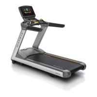
4) Disconnect the brake and both fan wire connections (Figure A). NOTE: BEFORE REMOVING THE BRAKE AND FAN PLATE, BLOCK THE
STAIRS FROM ROTATING (place a block under the bottom stair) TO PREVENT INJURY.
5) Remove the 4 screws holding the brake and fan plate to the drive set (Figure B) and remove the assembly.
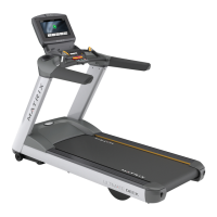
6) Remove the cable ties holding the ECB wiring to the drive set (Figure C).
7) Loosen 2 screws to remove the nut standoffs off the ECB (Figure D).
FIGURE C FIGURE D
FIGURE A FIGURE B
 Loading...